


ElmorLabs PMD Review
If you are into overclocking and tech testing then you should check the ElmorLab website. They have handy devices and equipment for the enthusiasts/serious overclockers. We are taking a look at PMD from ElmorLab. PMD stands for Power Measurement Device and it shows the real-time power draw of the CPU and the graphics card which is a must-have for the tech testers and overclockers. This device can be purchased at $45 from their website with worldwide shipping available. The device measures the voltage, current, and power being consumed by the CPU and the graphics card from their inputs. They have included an OLED screen that displays the power consumption of the selected input source. There is a toggle button to switch between the input sources and monitoring options.
Specification
- 2x EPS 8-pin (CPU) and 3x PCIE 8-pin (GPU) power inputs from power supply
- 5x custom output connectors for use with included cabling
- PCIE1, EPS1, EPS2 channels 0-15.5 V 0-60 A, with max 30 A continuous load
- PCIE2 (dual input) channel 0-15.5 V 0-60 A, with max 50 A continuous load
- OLED screen displaying overall power consumption or power, voltage and current per channel
- I2C connector for extended readings, logging and oscilloscope functionality (up to 10 ksps)
- Menu options for offset calibration, timeout behavior and I2C address selection
Packaging and Unboxing
The device comes in a cardboard box in brown color packing.

There is an ElmorLabs branded sticker pasted on the top of the packing box. There is nothing else on any side of the packing box.

Opening the box will show the contents.
Contents
Following are provided in the box:

- PMD circuit board
- Acrylic case including mounting hardware
- OLED display
- 2x EPS 8-pin output cables
- 3x PCI-E 8-pin output cables
- 1x I2C cable
Closer Look
Let’s take a look at the device.

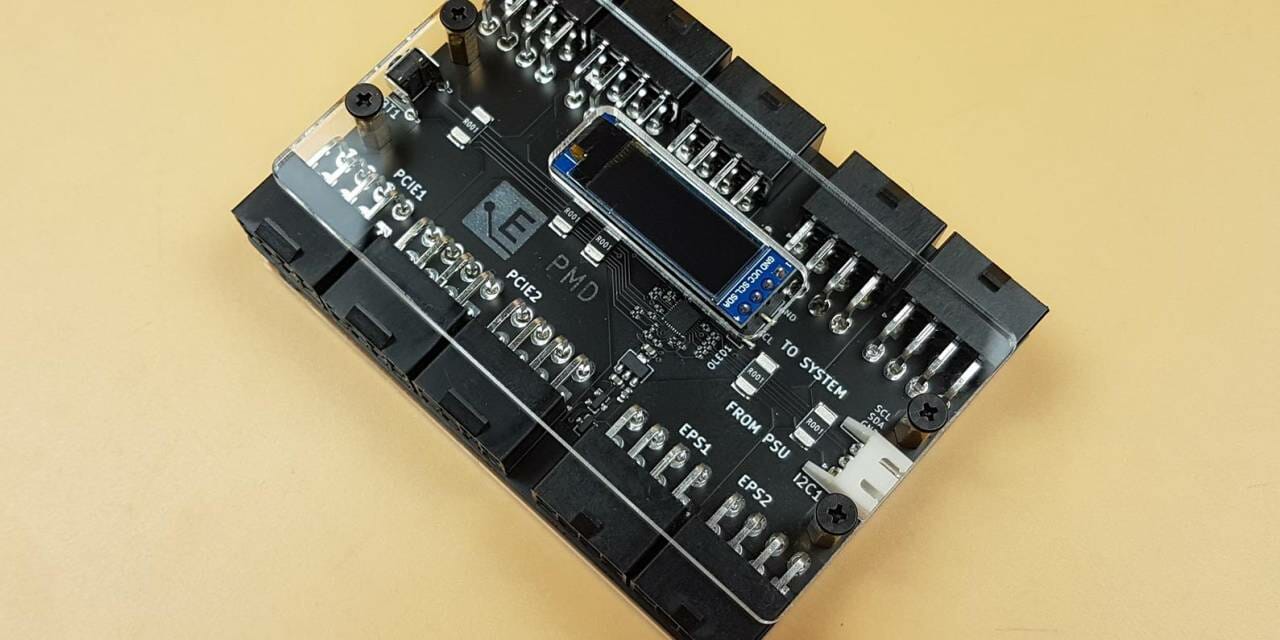
The backside of the device shows a nice soldering job done for the terminals. There are two mounting holes on each side. These are there to install the acrylic case on the device.

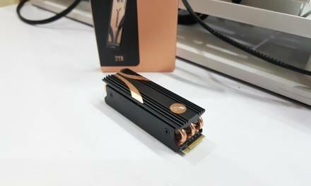
ElmorsLab is using a black color PCB. We have a total of 3x PCIe connectors and 2x EPS connectors. This device sits between the CPU and the components (CPU and Graphics Card). The PEG and EPS cables from the PSU are connected to the side of the PMD. The provided PEG and EPS cables in the PMD box are connected to the opposite side of the PMD. The EPS1 and EPS2 channels have a voltage range of 0-15.5V with the current range of 0-60A, with a max of 30 A continuous load.

There are 2x Labels in the white color. These are “To System” and “From PSU”. The cables from the PSU are connected to the connectors facing the label “From PSU”. The bundled cables in the PMD box are connected on the side labeled “To System”. This is important so pay attention, please.

There is an I2C1 connector on the side of the PCB. It is white in color and has 3-pins. ElmorLabs has provided a cable in the box which allows the user to connect the PMD to the EVC2/EVC2SX devices which can be purchased separately. The EVC2/EVC2SX modules provide even more functionalities and also software-based monitoring. The graphical output would be easier to show in the contents. The Oscillation feature is also provided (up to 10ksps).

There is a black color toggle button on one side of the PCB labeled as BT1. It can be used to switch the monitoring of the input terminals as well as the monitoring options.

There are a total of 3x 8-pin PCIe connectors. Please note that one is dedicated labeled as PCIE1 whereas the other two are combined as dual input labeled as PCIE2. The dedicated one has a voltage range of 0-15.5 V with a current range of 0-60 A, with a max of 30 A continuous load. The PCIE2 (dual input) channel has a voltage range of 0-15.5V and a current range of 0-60 A, with a max 50 A continuous load. This implies that we can’t monitor the power consumption of all three terminals individually. Since these are in channels so we can monitor the power consumption of two channels.

The ElmorLabs has provided an OLED display screen that can be connected to the PMD on a 4-pin black color header. This screen outputs the power consumption in real-time. The PMD serves no purpose with this OLED screen. This screen would not be needed if using the EVC2/EVC2SX modules.

Make sure to match the GND and SCL labels on the PCB of PMD and on the OLED screen. Hence the OLED screen can only be installed in one position.

The PMD is using ATSAMD10C13 ARM Cortex-M0 based microcontroller at its core which is a 14-pin SOIC.

There are two Acrylic plates provided in the box. They have brown color protective covers on them which can be peeled off. The larger-sized plate is to be installed on the backside of the PMD whereas the small size plate is to be used on the top of the PMD.

The above picture shows the acrylic top with a protective sheet peeled off.

There are 2x EPS cables (for CPU) in the box. They are flat in design and have a length of 480mm.

There are 3x PEG cables (for Graphics Card) in the box. They are also flat in design and have a length of 480mm.

There is an OLED display screen module provided in the box. There is a protective cover on the screen which can be removed by handling the blue color cover.

The above picture shows the underside of the OLED PCB.

The module has 4-pin connectivity.

There is a dedicated cable provided in the box to utilize the I2C1 connector’s functions.

This cable has a 3-pin white connector that is connected to the I2C1 header on the PMD. The 3-pin black/gray color connector is for the EVC2/EVC2SX module.

The above picture shows the mounting hardware to install the acrylic panels on the PMD. There are 4x rubber feet as well. The attention to the details is appreciable.

The above picture shows the PMD with all 5x cables connected to the side labeled as “To System”. These are the cables that are provided in the PMD packing box. One side of these cables is connected to the PDM and the other is connected to the EPS header(s) of the motherboard and graphics card’s connectors.
Installation of Acrylic Case

The installation of the Acrylic case is a simple process. Pass the threaded side of the golden standoff from the backside of the PCB’s mounting holes and secure it using the other piece of the golden standoff as shown in the picture.

The above picture shows the standoff with a longer length on the top of the PMD after installation.

Place the large size acrylic plate on the backside of the PMD such as the mounting holes on the acrylic plate facing the standoffs. Use the black color Philips screws to secure the acrylic plate on the back of the PMD.

Paste the 4x rubber feet on the corner of the acrylic plate.

Repeat the process for the small size acrylic plate on the top side of the PMD. The cutout on the acrylic plate should face the OLED display screen. Please note that the top plate covers the PCB portion and some of the connectors’ surfaces, leaving enough room on the connectors for convenient handling.

The above picture shows the side view of the fully assembled device.
Testing
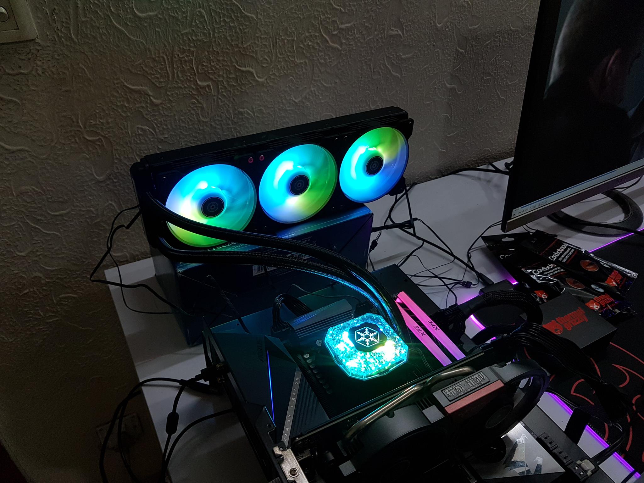
We have used the following testbed to check the functionality of the PMD:
- Intel i7 10700k [4.7GHz at 1.25V]
- Noctua NH-U12A
- MSI MAG Z490 TOMAHAWK
- MSI GeForce RTX 3090 Gaming X Trio
- T-Force NIGHTHAWK RGB DDR4 16GB @ 3200MHz
- addlink S70 256GB NVMe drive
- be quiet! Straight Power 11 850W Platinum PSU
- PrimoChill Praxis WetBench
We have used AIDA64 Extreme 6.33 and MSI KOMBUSTER to check the CPU and graphics card’s individual as well as the total power draw under load.

The above picture shows the PMD with both sides cables connectivity.

The above picture shows the complete setup.

Both components were drawing 55W when booted up in the windows.
CPU Power

The CPU was drawing 168W under load with all cores clocked at 5.1GHz using 1.345V. 14A was being drawn at 12V.

The total power draw of both components was 179W.


The graphics card was drawing 369W power combined (less the PCIe slot) under furmark load. Please note that the PMD only reports the power draw from the connectors. It does not include the up to 75W power provided by the PCIe slot on the motherboard. We were using GPUZ for the sensor log.
Combined Power Draw

The combined power draw of both the components under load is 509W. This does not include the PCIe slot power consumption of the graphics card.
Conclusion
PMD (Power Measurement Device) from ElmorLabs is a handy tool to monitor the power consumption of the CPU and the graphics card in real-time (using power inputs). The device has a total of 3x 8-pin PEG connectors in two channels and 2x 8-pin EPS connectors in two channels. Each EPS1, EPS2, and PCIE1 channel has a voltage range of 0-15.5V with the current range of 0-60A with the total continuous output of 30A load. The dual-input PCIE2 channel has a voltage range of 0-15.5V with the current range of 0-60A with the total continuous output of 50A load. The device has the capability of measuring a total of 1680W load continuously.
The PMD has a black color PCB and is well laid out along with a good soldering job. The device comes with 3x PEG cables and 2x EPS cables. These cables have a length of 480mm and are flat in design. The connectors’ sides are properly labeled which would help the user in the installation. ElmorsLab has also provided an OLED display screen which is to be connected to the 4-pin header on the PMD. The toggle button switches between the monitoring options which are displayed on the OLED screen. There is an I2C1 connector on the PCB along with the supported cable which allows the user to connect the PMD with EVC2/EVC2SX module (can be purchased separately). The EVC2/EVC2SX allows the software-based logging and monitoring of the voltage and current readings.
The idea is simple. The PMD sits between the PSU and the components (CPU and graphics card). ElmorLabs has provided 5x cables that connect the CPU and Graphics card to the PMD. The EPS and PEG cables from the PSU are connected directly to the PMD. ElmorLabs has provided acrylic plates to serve as the case for the PMD along with the mounting hardware.
Please note that PMD only reports the power draw through the input terminals. While this is ok for CPU power monitoring, it has implications for graphics card monitoring. We know that the graphics card also draws up to 75W power from the PCIe slot of the motherboard. That power draw is not monitored and reported by the PMD. So, we still have to rely on software like GPU-Z sensor log to know the power draw from the PCIe slot and add it to the power output provided by the PMD. Hoping to see a solution from the ElmorLabs to measure the complete power draw of the graphics card across the board!
We have used the PMD to monitor the power draw of the Intel i7 10700k at 4.7GHz all cores using 1.25V and MSI GeForce RTX 3090 Gaming X Trio. The PMD reported the power draw of the CPU to be 168W and the graphics card power draw without PCIe slot power input to be 369W. The device is doing what it is supposed to do. The PMD can be purchased from ElmorLab’s website where the device is listed at $45. This is a must-have for the tech testers and overclockers when it comes to measuring the real-time power draw of the CPU and graphics card without relying on the software.


