


Noctua NA-FC1 Fan Controller Review
Introduction
We will be taking a spin on a handy accessory from the Noctua which is NA-FC1. It is a slim fan controller which allows the user to control up to 3x PWM fans. The controller can work with the motherboard for the PWM signal as well as can work as a standalone controller. The controller has a speed dial to regulate the PWM duty cycle. The NA-FC1 is listed at $24.15 on AMAZON US and £24.11 on AMAZON UK.
Specifications

Closer Look

The foams are shipped inside a paper board packing box.

The presentation of the product is quite effective. We can spot the controller. The content list is printed on the leaflet.
Here is what the Noctua is saying about these, “The NA-FC1 is a compact, highly flexible controller for 4-pin PWM fans that can both work on its own for manual speed reduction and also work in tandem with the automatic motherboard fan control. By adjusting the NA-FC1’s speed control dial, users can either manually set a PWM duty cycle from 0 to 100% or reduce the PWM duty cycle supplied by PC motherboards in order to have the fans running slower than the automatic motherboard fan control would allow. While the brightness of the orange status LED provides visual feedback on the current dial setting, the push button allows the NA-FC1 to be switched into “no stop” mode, which prevents the fan from falling below a speed of 300rpm. Thanks to the supplied 3-way split cable and power supply adaptor, up to 3 fans can be controlled simultaneously.”

The dimension of the controller is 21x25x48mm. It is a slim form factor controller which makes its installation and handling convenient inside the PC Case. We have two LED indicators on the top. One is in the Orange color and the other is in the green color. These indicate:
- Orange LED indicates the speed setting in terms of brightness. The more brightness would show the maximum PWM duty cycle being applied.
- Green LED indicates the “No Stop” mode status. If it is on then the fans are in no stop mode. Off would mean normal mode.
Then we have a speed dial button below the LED indicators. This button sets the PWM duty cycle between 0 and 100% in manual mode (when the controller is working standalone) or adjusts the input signal from 100 to 0% in motherboard control mode.
Then we have a No Stop Mode Push-button. It is a toggle button that would either turn the No Stop mode on or off with the push. If the controller enters the No Stop mode the Green LED would light up.
At the base of the controller, there is a 4-pin connector. This is an output connector that is connected to the fan or multiple fans using splitter cables.

The above picture shows the opposite side of the controller with a 4-pin Input connector. Noctua has provided a cable labeled NA-EC1 which is to be used to connect the controller with either the motherboard or other power source.

There is a Noctua branding on the underside of the control box.

The above picture shows the NA-EC1 cable. The socket port will be connected to the input port of the controller. The 4-pin header is where the connection from the motherboard or another power source will be connected to.

The above picture shows the connector and header of the NA-EC1 cable.

The above picture shows the NA-EC4 cable provided with the NA-FC1. This cable connects the controller to the power supply using the SATA connector and the motherboard. The motherboard connection is for the PWM signal or input to and from the controller. If you are using powerful fans like Noctua NF-F12 3000 iPPC PWM fans with a higher power draw then use NA-AC4 so that the power factor can be taken care of. Similarly, use this cable for third-party fans which would require more power. This is in the context of the power rating of the fan header on the motherboard. Usually, the fan headers are rated for 1Amp and 12W. Whereas some motherboards like GIGABYTE boards are using 2Amp and 24W power ratings for the fan headers. When we daisy chain the fans and connect them to a single fan header, we need to be sure that the combined power draw of the fans does not exceed the maximum power rating of the fan header otherwise it would damage the motherboard and the fan. Using a power supply adapter, we provide the power to the fans directly from the PSU and use the fan header for PWM signaling only.

The above picture shows the connectors and header of the NA-AC4 cable.

Noctua has also provided a 3-way PWM splitter cable called NA-SC1. As the name suggests, this cable allows up to 3 PWM fans to be connected to a single source.
Connectivity Options
There are two ways in which the user can set up the controller.

The above picture is showing one of the ways. We can connect the NA-EC1 cable to the controller on the input side and connect the NA-SC1 cable to the output side. The NA-EC1 header can be connected to the fan header on the motherboard for PWM signaling.

The above picture is showing the second way. We can connect the NA-AC4 to the Input side of the controller and the NA-SC1 cable to the output side. This would be required when the fans being used draw more power than the rated power of the motherboard’s fan header. The SATA connector will take power from the PSU directly. The 4-pin PWM connector will be connected to the 4-pin PWM header on the motherboard for PWM signaling.
Please take a note that if you want to use a single fan then an NA-SC1 cable is not needed and you can directly connect the fan to the output side of the controller.
Modes of Use
One would need to understand a few basics of the controller and its mode of working to get the maximum benefit out of it. We have two modes defined for this controller:
- Manual Control
- Automatic Motherboard Fan Control
- No Stop Mode
Manual Control
The NA-FC1 is designed to take the PWM input signal from the motherboard by default. This implies that the controller would work in the automatic fan control mode. If the controller does not receive any PWM input signal on the NA-EC1 cable, then the controller will come in the manual mode configuration for which the NA-EC1 will generate the PWM signal from 0% to 100% duty cycle and start controlling the connected fan(s) via its speed knob or dial button. You can rotate the dial clockwise to increase the speed of the fans or anti-clockwise to reduce the speed.
If you would want to have the controller operate in manual mode at all times, you would need to disable the automatic fan control in the UEFI/BIOS and this would make the NA-EC1 tell the controller to enter the manual mode.
Automatic Control
If NA-EC1 receives a PWM signal from the motherboard, it will inform the controller about the input signal. Now, we have a situation in which there will be two signals. One will be coming from the motherboard via NA-EC1 and the other would be on the controller from the dial knob. This could create a conflict. For this, Noctua has designed the controller in such a way that the NA-EC1 will adjust the PWM duty cycle from 100% to 0% depending upon the setting on the dial knob on the controller.
To make it understand, let’s suppose that the dial knob is set at 50% whereas the motherboard is supplying 100% duty cycle. The NA-EC1 will adjust the input signal so that the output remains near 50%. This way the controller works in conjunction with the motherboard to reduce the original fan curve speed as per the user requirement. The user requirement here would mean the settings on the dial knob.
“No Stop” Mode
Regardless of the control mode the controller is working in that is Manual or Automatic adjustment of the input PWM signal, lowering the dial knob to the lowest possible may make the fan(s) stop working provided the fan(s) features the Zero RPM mode. If you would want the fans to continue working, you can press the “No Stop” button on the controller. This would make the controller not let the fan(s) speed fall below 300 RPM. This 300 RPM is a pre-defined setting in the controller firmware. There are many fans in the market who have the lowest speed rating of 500 RPM or above. For such fans, the “No Stop” mode is not needed as the fans would not fall below the 300 RPM on which the controller would make them stop. It would roughly take 30 seconds to when a fan is brought up to 300 RPM in “No Stop” mode.
Installation

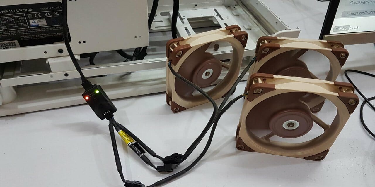
The above picture shows the 3x Noctua NF-A12x25 PWM fans connected to the NA-FC1 using the NA-SC1 splitter cable. Each fan draws 0.14A. This means the combined power draw of the fans is less than the 1Amp. The fan headers on the GIGABYTE Z690 AERO G are rated for 2Amps max per header hence we were safe in using these fans without the NA-AC4 cable.

The above picture shows the controller in action. The orange color LED is brightened showing the high speed of the fans. The green color LED is also on meaning the controller will not let the fans stop. The user can rotate the dial knob to up or down the speed of the fan using the PWM duty cycle.

Take a note of the speed of the System_Fan4 in the monitor. The RPM is 0. We pushed the No Stop mode button and it activated the Zero RPM function on the controller. The fans come to cease as can be seen in the picture. Also, take note of the orange color LED. It is no longer lit up as well showing the 0% duty cycle.

Next, we pushed the No Stop mode button again and then exited the zero RPM mode. We did not use the dial knob and the fans came back on automatically within a few seconds. Take a note of the RPM reading on the monitor. The orange color LED is still off because the dial knob was set to 0% duty cycle.

The above picture shows the close-up of the LEDs when entering the No Stop mode on the controller.
Testing
The following configuration is used:
- Intel i7 12700k [Auto, Stock]
- PCCOOLER GI-56UB
- GIGABYTE Z690 AERO G
- XPG Lancer RGB 6000 32GB DDR5
- Sabrent Rocket 4 Plus 2TB PCIe 4 NVMe SSD
- Noctua NF-A12x25 PWM 3x Fans
- Noctua NA-FC1
- be quiet! Straight Power 11 850W Platinum
- Thermaltake Core P6 TG Snow Edition in an open-frame layout
We have used 3x Noctua NF-A12x25 PWM fans which are rated for up to 2000 RPM at 100% Duty Cycle to test with the Noctua NA-FC1. The NA-FC1 was found working flawlessly and the fans were responding to the dial knob with adjustment in the input signal.
Conclusion
Noctua NA-FC1 is a handy PWM fan controller from the manufacturer which is designed to control up to 3x 4-pin PWM fans. The controller has a slim outlook standing at 21x25x48mm in black color housing. There is a speed dial knob that is used to change the PWM duty cycle. Please note that we are talking about the PWM duty cycle not the speed of the fan in terms of RPM as different fans will operate different RPMs at the same duty cycle. The maximum rated current is 3A and can handle Noctua 12V and 5V fans as well as third-party fans.
Many motherboards provide insufficient options to customize automatic fan control or simply don’t go below certain duty cycles and speed levels. Using the NA-FC1, the user can lower the motherboard’s PWM control curve in order to achieve silent operation.
By rotating the knob clockwise, the PWM duty cycle is increased and it is reduced in the anti-clockwise direction. There is also a “No Stop” button on the controller which will make the controller not let the connected fans achieve Zero RPM. We have two LED indicators on the top. The brightness level of the orange color LED will show the PWM duty cycle. The green LED indicator will light up when No Stop mode is activated.
The controller has a 4-pin input connector on the top and a 4-pin header on the base for output. Noctua has provided the following cables with the controller:
- NA-EC1 to connect the controller with the motherboard for the PWM signal.
- NA-AC4 with power supply adapter to connect the controller with the motherboard for PWM signal and SATA connection with the PSU for the power. This cable has to be used when the combined power draw of the connected fans exceeds the power rating of the fan header on the motherboard.
- NA-SC1 allows the 3 fans to be connected to the controller at a time.
The controller is a smart design that adjusts the incoming PWM signal from the motherboard to the dial knob setting specified by the user. In case of no input signal from the motherboard, the controller will act in a manual mode and regulate the speed using the dial knob. If the fan(s) speed lowers below 300 RPM, the controller will make the fans to stop. The user can push the “No Stop” button to avoid this. This is only applicable if the fan has the lowest speed rating of 300 RPM or below.
The NA-FC1 has a retail price of $24.15 and £24.11 on AMAZON US and UK respectively at the time of the review. Noctua is offering a 6-years warranty on the NA-FC1. We have tested the NA-FC1 using the 3x Noctua NF-A12x25 PWM fans and found the controller working flawlessly under both control modes. This is a handy dandy accessory and comes recommended by us.
Thanks to Noctua for supplying NA-FC1 for testing.


