


Thermaltake Toughpower DPS G RGB 750W PSU Review
Introduction
- Manufacturer: Thermaltake
- Product Page: Thermaltake Toughpower DPS G RGB 750W Gold
- Purchase: £136.49 At the time of review on Amazon UK
Power Supply Unit (PSU) is the most critical yet easily overlooked component of any PC build. There is much more to PSUs than converting main ACs to low-voltage regulated DC powers for the components of the PC. At present PSU market is filled with wide range of products. It has been a trend that users focus on the Watts requirement disregarding safety features, quality of components used inside the PSU. Now, this trend is changing as users are becoming aware of all the necessary and important criteria required for PSU selection.

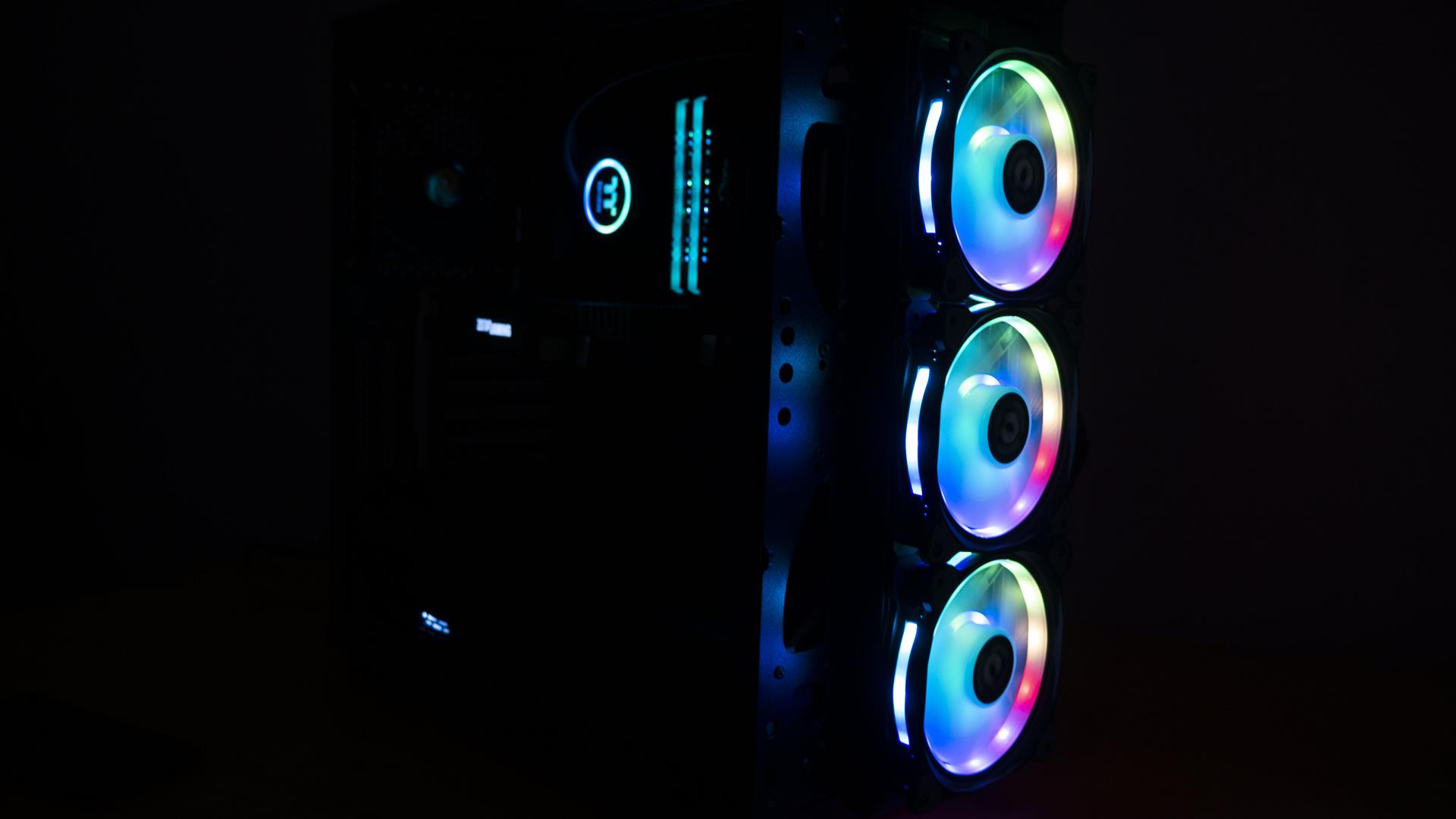
When it comes to PSUs, my take on them is different. I would consider every other purchase in the PC components as just a cost but the price that I would pay for the PSU is the investment to safeguard the other expenses incurred on the purchase of the PC components. Today we’ll be reviewing a ToughPower DPS G RGB 750W PSU from Thermaltake. This unit is a fully modular one with an 80+ Gold rating and it is digital as well employing a fully dedicated 32 bit MCU. It has a 140mm RGB LED fan to give more pleasing looks though these looks are subjective. Plus, this unit can be monitored and controlled using cell phones thanks to Thermaltake’s implementation of Cloud based computing using Smart Power Management (SPM) architecture. The deployment of a powerful, 32 bits Microchip microcontroller PIC32FMX has enabled the unit to add valuable and intelligent features:
- Real-time data exchange with Thermaltake Smart Power Management software.
- High-frequency PWM and variable duty cycle generation on the fly enhances the control dynamics.
- Analogue to Digital Converters for necessary feedback to switch among several modes of power supply.
- Primary and Secondary Power monitoring with dedicated power supervisor chip.
- Fan speed Control.
Specifications
| Part No | PS-TPG-0750DPCG-R |
| Short Part No | TPG-0750D-R |
| Model | TPG-750DH3FCG-R |
| Type | Intel ATX 12V 2.31 & SSI EPS 12V 2.92 |
| Maximum Output Capacity | 750W |
| Peak Output Capacity | 900W |
| Color | Black |
| Dimension (W / H / D) | 150mm x 86mm x 180mm |
| PFC | Active PFC |
| Power Good Signal | 100-500 msec |
| Hold Up Time | > 16ms at 70% load |
| Input Current | 10A |
| Input Frequency Range | 47Hz – 63Hz |
| Input Voltage | 100v – 240v |
| Operating Temperature | 0 ℃ to +40℃ |
| Operating Humidity | 20% to 90%,non-condensing |
| Storage Temperature | -20 ℃ to +70 ℃ |
| Storage Humidity | 5% to 95%, non-condensing |
| Cooling System | 14cm RGB Fan |
| Efficiency | MEET 80 Plus GOLD at 115Vac input. |
| MTBF | 120,000 hrs minimum |
| Safety/ Approval | CE, TUV, FCC, UL/CUL, BSMI |
| PCI-E Connector | PCI-E 6+2pin X 4 |
| Protection | OCP, OPP, OVP, UVP,OTP, SCP |
Packing
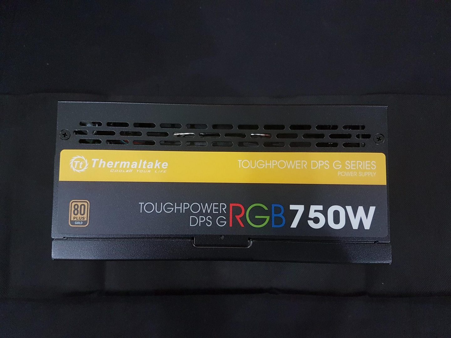
Unit comes in an attractive and colourful cardboard box with dark yellow (almost golden) and black colors. Top of the box is in dark yellow colour with Thermaltake and model name of the unit printed in white. Some salient features of the PSU are printed on the front. Picture of the unit is printed particularly showing the top and the back side. The fan is illuminated in multipcoloursors to signify the RGB LED lighting on it.

“VR READY TT POWER” catches my eyes and left me thinking what would a PSU has to do with VR Readiness besides giving an impression that PSU is ready to provide stable power to VR Ready components in the build. While one would expect VR Ready tagline on the graphics cards, we are seeing a PSU unit carrying it. Here is what company is saying about it “Toughpower DPS G RGB Series power supplies offer stable and sufficient output voltage for multiple VGA cards and high Capability of different VGA cards for VR system.” This seems more of a Marketing Gimmick than anything else.
Unit is 80+ Gold certified with efficiency level of 91%. 80 Plus is a voluntary certification that classifies the PSUs by their efficiency levels. Idea was to promote the energy efficiency consumption by encouraging the manufacturers to produce units with efficiency of 80% and above at 20%, 50%, 100% of the units rated load. It also takes into consideration power factor which should be 0.9 or higher at 100% load. All this to ensure that less heat is generated in wasted energy; this would also put less stress on the utility bills.

Backside of the box has crucial information printed on it like the connector types and their quantity on the right top section. Below it, we have printed Output Specification, part no label on the bottom. The entire left portion of backside provides information on Cloud based monitoring and controlling the unit using DPS G PC App and DPS G Mobile App plus web-based interface. Software is covered in the last section of the review.

Left and right sides of the box signifies the SPM (Smart Power Management) Service Architecture and its implementation. SPM offers “Three Screens and a Cloud” service to the users to monitor and record the status of Power Consumption, Voltage Distribution and electricity cost.

Bottom section of the retail packing has 80+ Gold Certification and Digital usage printed in 12 different languages. Here, we made an interesting observation. Printed text indicates that unit is prepared for the new Intel processors Haswell to achieve maximum energy savings. Whereas the info on their website under this product goes like, “Additionally, Toughpower DPS G RGB 750W Gold has been optimised to work with Intel’s new, sixth-generation Skylake processors to achieve maximum energy savings.” This is something for Thermaltake to consider changing.
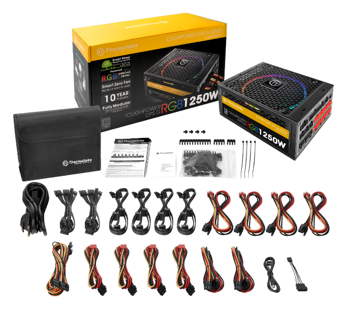
Opening the box would reveal the contents. The unit itself is wrapped inside a cloth with Thermaltake logo acting as seal stamp and placed inside foam pads for protection. There is a nice pouch containing all the cables. Printed material includes a user guide, warranty guide, software guide.


Closer Look
Cables
This PSU is fully modular. The modular approach has made it convenient for the users and saved them the hassle of dealing with all the cables clutter. Now, users can connect only the required cables and keep the not needed cables away. This would help in better cable management and improve airflow (later is a subjective term).

Cables provided with this unit are flat and not sleeved. Personally, I like the flat cables approach as they make the cable management task bit easier and gives more clean looks.

Here is the info regarding the cables for this unit:
| Type | Quantity (No) | Length (CM) |
| Main Power Connector 24 Pin | 1 | 60 |
| ATX 12v (EPS) [4+4] | 1 | 60 |
| PCI-E 6+2 Pin | 4 [2 cables with two connectors per cable] | 60 |
| SATA 5 Pin | 8 [2 cables with 4 connectors per cable] | 100 |
| Peripheral (Molex) 4 Pin | 8 [2 cables with 4 connectors per cable] | 80 [Approx] |
| FDD 4 Pin | 1 | 10 |
In addition to above, we have the main power cable and a USB cable. USB cable is connected to any USB 2.0 header on the motherboard to enable the digital monitoring of the unit. PCIe connectors are in red colour. Colour coding is helpful in identification of PEG cables from EPS cables.
Unit Design
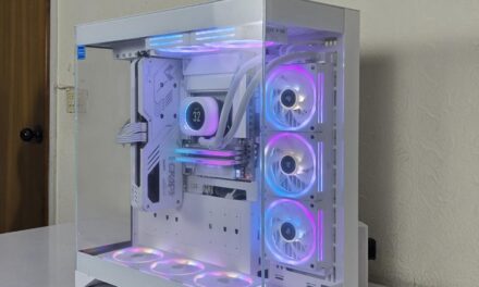
The unit itself measures 180mm length, 150mm wide and 86mm height. The unit is in black colour. Top of the unit has typical Thermaltake design with steel vents for airflow. The unit employs a 140mm RGB Fan. The concentrated compression blade on the fan is engineered to focus the weaker, inner circle of air outward, allowing the outer section to pressurise the air. The fan blades are optimised to enhance static pressure for an impressive cooling performance. Hydraulic bearings for silent operation guarantee ultra-low noise, and the anti-vibration mounting system strengthens the product’s stability during operation. Moreover, In-mold injection anti-vibration rubber pads provide hassle-free usage for 80% protection coverage, including all four corners.

There is a squared large size Thermaltake logo in the middle. It is placed such that it is right on the top of the 14cm fan’s middle. We can see the Warranty Void Sticker on the right most side.
Left and Right side of the unit has stickers pasted on them. The sticker is in dark yellow and black colours. Overall, the sticker does look good and pleasing to the eyes. No complaint there. To signify the RGB lighting, term RGB is written in 3 colours with R in red colour, G in green colour and B in blue colour.

The back side of the unit has a notice posted on it which mentions that fan will not spin if the unit is under 20% of the load. We can see the same steel vented design on the back side as that is on the top. This is to ensure the effective heat dissipation and air flow. We’ve standard mounting screw holes on the backside to ensure the compatibility with any chassis. A standard 3 pin AC Power Cord header with a switch (on/off) button is on the middle right side. Please take note if the switch is on 0 then unit will remain off even if it is getting power from the wall. To power on the PC, turn the switch to 1.

The IO side of the unit is very well laid out. We’ve Thermaltake logo and brand name printed on the upper right most side. A USB header is on the top left side. The supplied USB cable is connected on this header to enable the digital monitoring of the unit. I’ve found this implementation much simpler than Corsair’s implementation on their digital PSUs.
All headers are clearly labelled and are divided into two groups. On left most side we’ve 24-Pin ATX header and the second group has all other headers. One just can’t go wrong while connecting cables on these headers. 24-Pin ATX header is implemented in 14+10 header right below the USB header. PCI-E headers are in red colour for easy identification.
We’ve 4 Peripheral (Molex) and SATA headers each being 6-Pin, 2 PCI-E and 1 EPS headers. PCI-E headers are 8 Pin ones (6+2) whereas EPS header is 8-Pin (4+4). There is no bunch of wires coming out from anywhere as the unit is fully modular and it is up to user to use the required cable.

The bottom side of the unit has all the technical information printed on the label. The unit is Hi-POT Ok. For our those readers who may not be well-versed with this term, Hi-POT stands for High Potential and in simple words, it indicates that unit has been tested and verified for electrical insulation using electrical safety testing instruments. The unit is Q.C. passed. We’ve a label for unit identification on the top left side.
The dark yellow colour sticker has Thermaltake brand name, logo, model and part no of the unit printed on it. The black colour sticker has the output specification, warranty info, 80 PLUS info, safety/approval info. There is a warning on the bottom informing the users that unit is not user serviceable and should be returned in case of any fault. This is because the unit has hazardous voltage contained within it.
Output Specification
| AC Input | Input Voltage: 100v – 240v
Input Current: 10A Frequency: 47HJz – 63Hz |
||||
| DC Output | +3.3V | +5V | +12V | -12V | +5VSB |
| Max Output Current | 20A | 20A | 62A | 0.8A | 3.0A |
| Max Output Power | 100W | 744W | 9.6W | 15W | |
| Total Power | 750W | ||||
This unit has a single +12V rail with 62Amps on it. It is enough to power a system with 2-way SLI/CF of the graphics cards subject to graphics cards’ power requirement. We’ve tested the PSU on X99 platform with SLI of EVGA GTX 1070 FTW Hybrids and did not see any issue at all. Maximum power draw was 560W which still leaves plenty of headroom should there be the requirement of other accessories or components. Bear in mind that PSU was powering Asus Rampage V Edition 10, i7 6850k, 2 SSDs, 1 HDD, 4 fans and a 560W draw was with heavy overclocking on CPU and Graphics Cards.
The user guide has one warning to the users which is that warranty will void with the use of the third party modular cables and users should only use Thermaltake modular cables. Though this is to ensure the maximum compatibility and to reduce the risk of damage but this is not user-friendly warning as these days we are seeing the majority of users, using fully sleeved custom coloured extension or full-length cables to add pleasing looks to the builds from various vendors.
Protection and Safety Features
When buying a PSU, users must give a due consideration to the rated safety and protection features of the particular unit as a slight negligence can put the expensive machine at higher risk of getting damaged. This is where these safety features come handy. Ideally, as soon as any short circuit or surge is detected, PSU should shut itself down before the damage occurs on the components. After PSU, the most likely component to fail is motherboard because of the circuitry design but that puts the CPU at higher risk as well.
High-quality PSUs include protection features such as Over Voltage Protection, Over Current Protection, Over Power Protection, Short Circuit Protection, Under Voltage Protection, Over Temperature Protection etc. Usually, these features are mentioned as synonyms like OCP stands for Over Current Protection. Many users confuse OCP and SCP and use them interchangeably while there are differences between them.
This unit has OCP, OPP, OVP, UVP, OTP, SCP protections on it. Over Voltage Protection thresholds are as follow: –
| Voltage Source | Protection Point |
| +3.3V | +5.2V Max |
| +5V | +7.0V Max |
| +12V | +16.0V Max |
The unit will shut down and latch off if the Wattage of the power supply is 115% – 150% of continuous power. This is Over Power Protection feature.
EMI & Safety
| EMI Regulatory | MEET FCC |
| SAFETY Standards | MEET cTUVus, TUV bauart, CB, CE, CCC, BSMI |
Circuit Overview
Foregoing all in view, the qualitative review of power supply comprised of some parameters to assess and grade it in terms of efficiency, robustness, reliability, and its performance. To further stimulate the interest in readers, these parameters have been outlined as follows, on basis of their classification.
- Control dynamics of PSU features:
- Transient response
- Steady State response
- Load Regulation
- Cross Load Regulation
- Input and Output Power Quality is described by its:
- Harmonic Suppression and filtration at Input Power Cord
- Power Factor Improvement (Active and Passive)
- Power Efficiency (Switching Losses, Magnetics etc)
- AC Ripple Factor in secondary output voltages of the transformer
- Safety measures include:
- Dedicated Power supervisor chip at secondary side of transformer for OVP (Over Voltage Protection), UVP (Under Voltage Protection) and OCP (Over Current Protection) etc
- Fuse, MOV (Metallic Oxide Varistor) and relayed thermistor at Input Power Cord
- Proper Isolation of low and high power components on PCB, insulation and grounding
- Electromagnetic Compatibility
- Durability includes:
- Selection of components
- Proper Soldering
- Heat dissipation of components
- EMI (Electromagnetic Interference) Compliance
Few among the above-stated merits will be discussed to identify the cadre of the subject PSU. The most significant factor that determines the aforementioned parameters is the topology that is being employed in power supply for a particular application. However, there are fundamentally 6 sub-stages involves in shaping up an intelligent power supply unit.
- Input Harmonic Filter at the Input Power Cord (Impedance Matching, Insertion Loss and)
- Rectification (Full Bridge)
- Power Factor Improvement PCB (Active and Passive)
- Magnetics (Power Conversion)
- Transformer Secondary Side rectification, filtration and supervisory IC
- Embedded Control Board (Modular PCB)
All building blocks that are working together to form a complete unit being discussed are covered in upcoming paragraphs in relation to their performance.
Disassembly:
The top cover of power supply unit is removed from the bottom chassis which was fastened by 06 screws. Then, a patented noiseless fan, fixed underneath the top cover, is got detached from the Main PCB Board through 05 pins connector. This connector surely supplies the PWM (Pulse Width Modulation) signal for fan speed control and for customising LED blinking pattern.

Black colour, L-shaped PCB is then pulled off the nest, leaving the input AC power connections intact. Main PCB board is impregnated with further sub-PCBs of active PFC (Power Factor Correction), Synchronous Buck Convertor and MOSFET driver circuits. Power components are inductors, capacitors, ferrite core transformers and MOSFETs etc making up EMI filter, PFC, standby power supply and power conversion magnetics.

The input AC power is received by the input power EMI filter. EMI suppression capacitors are used to suppress any noise from the PSU by reducing the impedance of the PSU. These are classified as X and Y capacitors as shown in grey and blue colour respectively. Further, 02 inductor coils serve the same purpose. MOV (Metallic Oxide Varistor), unlike fuse which offers over current protection, it provides transient voltage surges by means of varying its resistance.

After filtering, 02 full bridge rectifiers are connected in parallel to convert AC to DC.

Now comes the modular PCB of active Power Factor Correction that is connected after the rectifiers. This circuit sits between the rectifier and polar capacitor in boost mode to purify the line currents from harmonics, generate by the high-frequency switching transformer. Being a part of PFC, a larger inductor coil is driven by CCM (Continuous Conduction Mode) PWM chip of Infineon through MOSFET switch. Active PFC, relative to passive PFC, remarkably brings the power factor closer to unity i.e. 0.9 that is the benefit of employing active instead of passive. However, as a sideline suggestion, PSUs armed with PFC, only comfortable to operate on sine wave power instead if ever be tried to run on a square wave by locally made UPS (Uninterruptible Power Supply).

The green colour thermistor is used as a protection from inrush current. It operates on the principle to increase its resistance high during high current. This is relay controlled thermistor as being shown in the below picture which overrides the thermistor to let it cool after getting done its job so that it be able to manage next inrush current.

Now comes the heart of PSU i.e. ferrite core main transformer that distributes the voltage to other modular 3.3V, 5V DC-DC level converter by shifting from one dc level to lower dc level. It is nicely wounded with insulation tape. In this power supply, its secondary is being synchronously rectified by the MOSFETs instead of diodes that sufficiently save it from switching losses, and enabling the unit to carry more current and handling capability of the power increases.

Synchronous rectification of secondary side 12 rail output of transformer with MOSFETs, instead of diodes since it is more efficient than later.

After conversion of 12 V, the same is fed to modular Buck Synchronous Converter to convert into 3.3 V and 5 V. Synchronous circuit employs the MOSFETs in place of the diode to reduce the switching loss, resulting from the very efficient power conversion phenomena. APW7159a chip, dual channel synchronous buck PWM converter by APNEC Electronics is used in PSU with M3004D MOSFETs.

Soldering is done shiny as seen in the appended picture below. Isolation is also perfectly done between the primary side and secondary side.
A power supervisor chip, on right side, is soldered at the bottom of the main board. This intelligently senses the over voltage, under voltage and over current and provides the signal to embedded controller PIC32 to switch the PSU in safe mode.
On the left side, the PWM controller is being shown to drive small standby transformer located at the top of PCB. This drives the MOSFETs M03N65D to generate stable 5VSB in a case of supply being operated in standby mode as signalled by CPU (C6/C7 states).

Modular Embedded Controller front PCB is provided with mini USB port along with output voltage sockets. USB port, as mentioned earlier, is used for the real-time data exchange with the smart power management software and with cloud database. 02 black wires branching off from the left side of microcontroller provide the requisite control signals to drive the secondary side MOSFETs for synchronous rectification. Purple cable depicting standby +5 V while other orange and red are 3.3 V and +5 V, respectively.
It contains solid capacitors. The one with pink marking is made by Enesol.

Lastly, an important account on an important component is about its selection of capacitors.
In power supplies, capacitors possess the critical place in defining its behaviour. They are susceptible to change their original behaviour due to their constant engagement with high power. Especially, their ESR values and temperature tolerance are important in deciding their ageing factor, endurance and reliability. The peculiar role of capacitor’s ESR value depends on the position of the capacitor in a power supply. For example, two important capacitors that use in power supplies are the capacitor which is soldered at the input filter after PFC and secondly, the capacitor that uses as an output filter after the main transformer secondary rectification.
The big brown capacitor bearing the value 470uF rated 400V accounts for filtering the ripples ridden DC power coming from the PFC switch. PFC switches sinusoidal DC signal at a high frequency which will make capacitor’s ESR (Equivalent Series Resistance) value susceptible to change with the passage of time. Furthermore, since PFC operates in boost mode to replicate the original sinusoidal signal from the distorted rectified signal, this pumped-up voltage renders PSU manufacturers to meticulously select the particular value and rating of the capacitor. In this regard, Thermaltake employs Japanese made with temperature tolerance of 105 °C that will efficiently serve its demanding role.

As indicated in the red box of appended picture, these capacitors discharge their filtration duty in the secondary side of the transformer and their ESR’s susceptibility to change inhibits the capacitor’s original role. Change in its ESR affects the voltage control loop stability of the main transformer. In this regard, Thermaltake has taken care of the aforementioned merit.

SPM Architecture
With their digital PSUs, Thermaltake has taken quite an innovative approach when it comes to monitoring real-time data. Usually, digital PSUs are provided with PC application to monitor the real-time data like various voltages, current on outputs etc. Thermaltake has taken the concept to a next level by introducing what they called Smart Power Management platform. It is a platform because we have a central database using cloud-based management, a PC Client (application) and a mobile phone app for monitoring and controlling the PSU. This would effectively mean that we have three interfaces instead of a single one. SPM is a cloud computing platform that tracks and analyses PC electricity consumption, allows the user to observe and learn their own energy consumption whereby alter their behaviour to achieve the goal of reducing CO2 emission together to contribute to slowing global warming.

The new DPS G PC APP 2.0 enables users to digitally monitor system information, such as efficiency, wattage, voltage, fan speed and temperature while using the computer. In addition, it will gather and upload the key parameters data to the SPM Cloud for further analysis. DPS G PC App is a PC Client application can be downloaded from their website https://dps.thermaltake.com/en/product. This is very comprehensive software which is giving user every bit of detail one could ask for.

This application provides handy interfaces for the users to monitor these critical readings.
3.3V Voltage reading
5V Voltage reading
12V Voltage reading
Current readings on each Voltage output in Amp
Power consumption in Watts
Temperature of the PSU itself
Power Consumption and temperature of the CPU
Power Consumption and temperature of the Graphics Card(s)
Efficiency reading
Fan Speed
Cost calculation
RGB Settings for the Fan
Each value can be taken as a number or in the graph format. One can change the temperature unit in C or F. Fan speed can be adjusted. RGB features of the fan can be accessed with this app. One can turn off the colour, have static colour from 256 colours spectrum or set it to change automatically.
The user can also provide the unit price of the electricity for kWh calculation. This would be handy as one can measure the total power consumption of a day or a week or a month and corresponding effect on the utility bill. Simply a great way to calculate electricity cost of the power consumed by the PC during a specific period. SPM keeps track of 90 days max.
One can even record the values and export them when needed in an Excel format for detailed analysis. The app will sync the data every 6 hours with a central database on the Thermaltake server using cloud computing.
Based on the comparison between Thermaltake’s DPS G app and Corsair Link, I’ve found DPS G to be more comprehensive and thorough. But, I also made an observation in the software. There is no mentioning of Min, Max, Avg values on the graphs as there is in Link software. Should Thermaltake implement these values, it would make DPS G to be a perfect solution.

DPS G SPM Cloud is a platform which offers the user the ability to monitor, analyse and access single or multiple computer systems data across the network through PC and mobile devices, as well as to socialise with other SPM users. One would need to create an account on dps.thermaltake.com to access the features.
Web-based interface provides a comprehensive analysis of the power consumption and allows the user to take print out of various charts and graphs showing average power consumption, efficiency etc.

Thermaltake’s focus is on the enabling the users to help contribute to lowering the CO2 emissions in an already troubled atmosphere of Earth. Users can set power saving goals and keep track of their power saving plans. The idea here is that by reducing the energy consumption, helps in reducing CO2 generation which is expressed in equivalency of how many plants one would have planted to gain the same level of CO2 reduction.


DPS G Mobile APP allows users to access, analysis and track single or multiple systems parameter information through mobile devices, plus the function to socialise with other SPM users. The app can be downloaded from respective platform’s store (Android, iOS) App name is Tt DPS G and it is compatible with iOS 7.1 and Android 4.4 or later. In order to use this app correctly, the user needs to be on the same network as of the respective PC. This app also allows the user to remotely restart or shut down the PC. DPS G smart software will send out a real-time warning signal to Mobile App when the fan speed, temperature (over 140F/60C) and Voltage (over/under 5% of normal level) operate abnormally.

In addition to DPS G Mobile App, we’ve another app which is DPS G Riing RGB app which can be used to remotely control the RGB function of the Riing fan of the PSU.
Final Thoughts
In today’s tough competition, Thermaltake seems to have provided what could be described as the best possible solution for powering any modern PC. With dedicated microcontroller for digital monitoring of the critical information coming from PSU, comprehensive software suite backing it all up, cloud-based computing, fully modular design, high-quality components inside, this unit offers much more than the user would have asked for. While the debate over RGB trend in the market continues, one can still buy this unit and turned the RGB light off and would still enjoy the other perks of this powerful unit. Many are advocating that with PSU fan side down or with non-vented PSU shrouds in the PC Chassis, this RGB addition is not welcome. Both arguments are valid but this is something one would need to decide upon when selecting the components for next PC build and deciding the airflow inside the chassis.
Value:
This unit is listed at $149.99 at the time of reviewing the unit. Price is on a high side for a 750W unit, particularly when in this price range Corsair’s Rm850x is in reach of the users. But one would need to bear in mind that this is a digital PSU for which Thermaltake has provided a fully dedicated micro-controller and has developed a comprehensive software package. RGB addition is a plus.
Performance:
The final verdict for Thermaltake RGB 750 W PSU speaks itself with having its rich features like synchronous operation of switch-mode converters providing lowest dissipation and AC ripples at especially + 3.3 V and 5.0 V, the special consideration for power factor by employing active mode of correction, dedicated intelligent power supervisor chip for output voltages, Japanese made capacitors with temperature tolerance of 105C along with featuring the power software management by employing powerful 32 bits Microchip microcontroller, this distinguishes it from its counterparts and stands aside with best results. Though we were not able to put the unit under lab test due to lack of adequate equipment (we are working on that part) but based on circuitry analysis, we have reason to believe that this is a high performing unit. We tested the unit on the X99 platform using Asus Rampage V Edition 10, i7 6850k, 64GB DDR4 RAM, SLI of EVGA GTX 1070 FTW Hybrids, Four fans, 2 SSDs and 1 HDD. Maximum reported efficiency was 92.8 which is almost near to 93% on our Corsair AX1200i PSU with the same PC. Bear in mind that Corsair PSU is 80+ Platinum whereas Thermaltake PSU is 80+ Gold. Maximum power draw as reported by the unit was 560W under load with heavy overclock on CPU and Graphics cards.

This PSU has won our Performance award based on total design element, modular approach, the comprehensive software suite for real-time data monitoring and use of high-quality components in the circuitry.
This review has been co-authored by Mr. Mohib Khan who is an Electronics Engineer. His area of specialisation is Embedded Systems and is currently working as a Design Engineer.
Special thanks to Thermaltake for sponsoring the review.


