


ASUS ROG Maximus IX Code Z270 Motherboard Review
Introduction
Intel announced its next-generation microprocessor architecture named Kabylake in Aug-2016. It represents a break from Intel’s Tick-Tock model which was deprecated in favor of “Process-Architecture-Optimization”. The new model would have three generations per process with a focus on optimization along. Kabylake is using a 14nm fabrication process. Intel has released a 200 series chipset on socket 1151 for Kabylake with Z270, H270, Q270, B250, and Q250 categories of 200 series chipsets.
Major differences between Skylake and Kabylake includes more clocks on the CPU with an approximately 300MHz difference at stock, 24 PCIe Lanes as compared to 20 PCIe lanes on the Skylake, Intel Optane Technology, Dual Channel Memory starting at 2400MHz, Graphics improvement by enabling 10-bit decoding on H.264. While there are 24 PCIe lanes off the chipset, the number of PCIe Lanes on the CPU is still 16. Having 4 more PCIe lanes from the chipset would be helpful when it comes to sharing the bandwidth among multiple storage drives interfaces.
Intel Optane technology is a new feature of 200 series platform and it is based on 3D XPoint memory media, Intel Memory and Storage Controllers, Intel InterconnectIP and Intel software. This technology intends to bring high throughput, low latencies with the high quality of service and endurance. Intel is releasing Optane based memory and SSDs for Prosumers/Consumers. Optane Memory needs not to be confused with System Memory. Optane Memory is an M.2 interface device which would sit between system RAM and storage drives to act as a high-speed cache much like software based caching. With Optane Memory, one can SSD like speeds with regular HDDs.
When it comes to PC Components, AsusTek is among one of the best names we have in the market. It was founded in 1989 in Taiwan. Ever since its foundation, Asus has seen a phenomenal growth and diversity in its business line. When it comes to Asus, the first associated name that comes to mind is ROG or Republic of Gamers. ROG brand was introduced in 2006 and it focuses on mainstream gamers/enthusiasts with products ranging from Motherboards, Graphics Cards to Peripherals. ROG is now mainstream, the premium brand from Asus. ROG Motherboards have always been the center of attraction from the enthusiast’s and gamers. Their Formula lineup is among the best ROG products out there. Today, I’ll be looking at their new Maximus IX Code motherboard.
Item: Maximus IX Code
Manufacturer: Asus
Price: $290/PKR 36,500/ £295.56 at the time of the review
Specification
| CPU | Intel® for 7th/6th Generation Core™ i5/Core™ i3/Pentium®/Celeron® Processors
Supports Intel® 14 nm CPU Supports Intel® Turbo Boost Technology 2.0 * The Intel® Turbo Boost Technology 2.0 support depends on the CPU types. * Refer to www.asus.com for CPU support list |
| Chipset | Intel Z270 |
| Memory | 4 x DIMM, Max. 64GB, DDR4 4133(O.C.)/4000(O.C.)/3866(O.C.)/3733(O.C.)/3600(O.C.)/3466(O.C.)/3400(O.C.)/3333(O.C.)/3300(O.C.)/3200(O.C.)/3000(O.C.)/2800(O.C.)/2666(O.C.)/2400(O.C.)/2133 MHz Non-ECC, Un-buffered Memory
Dual Channel Memory Architecture Supports Intel® Extreme Memory Profile (XMP) * Hyper DIMM support is subject to the physical characteristics of individual CPUs. * Refer to www.asus.com for the Memory QVL (Qualified Vendors Lists). |
| Graphics | Integrated Graphics Processor
Multi-VGA output support : HDMI/DisplayPort 1.2 ports – Supports HDMI with max. resolution 4096 x 2160 @ 24 Hz – Supports DisplayPort with max. resolution 4096 x 2304 @ 60 Hz Maximum shared memory of 1024 MB |
| Multi GPU Support | Supports NVIDIA® 2-Way SLI™ Technology
Supports AMD 3-Way CrossFireX™ Technology |
| Expansion Slots | 2 x PCIe 3.0/2.0 x16 (x16 or dual x8, gray)
1 x PCIe 3.0/2.0 x16 (x4 mode, black) 3 x PCIe 3.0/2.0 x1 |
| Storage | Intel® Z270 Chipset :
1 x M.2 Socket 3, with M Key, type 2242/2260/2280/22110 storage devices support (both SATA & PCIE mode) 1 x M.2 Socket 3, with M Key, type 2242/2260/2280 storage devices support (PCIE mode only) 6 x SATA 6Gb/s port(s) Support Raid 0, 1, 5, 10 Supports Intel® Smart Response Technology Intel® Rapid Storage Technology supports Intel® Optane™ Memory Ready |
| LAN | Intel® I219V
Anti-surge LANGuard ROG GameFirst Technology |
| Wireless Data Network | Wi-Fi 802.11 a/b/g/n/ac
Supports dual band frequency 2.4/5 GHz Supports MU-MIMO |
| Bluetooth | Bluetooth V4.1 |
| Audio | ROG SupremeFX 8-Channel High Definition Audio CODEC S1220
– Impedance sense for front and rear headphone outputs – Supports : Jack-detection, Multi-streaming, Front Panel Jack-retasking – High quality 120 dB SNR stereo playback output and 113 dB SNR recording input – SupremeFX Shielding Technology – ESS® ES9023P – Supports up to 32-Bit/192kHz playback *7 Audio Feature : – Gold-plated jacks – Sonic Radar III – Sonic Studio III |
| USB Ports | ASMedia® USB 3.1 controller :
1 x USB 3.1 front panel connector port(s) ASMedia® USB 3.1 controller : 2 x USB 3.1 port(s) (2 at back panel, , Type-A + Type-C) Intel® Z270 Chipset : 6 x USB 3.0 port(s) (4 at back panel, , 2 at mid-board) Intel® Z270 Chipset : *8 6 x USB 2.0 port(s) (4 at back panel, , 2 at mid-board) |
| ROG Exclusive Features
|
Clear CMOS button
ROG Armor ROG RAMCache II ROG CloneDrive MemOK! Button ReTry Button Safe Boot Button Start Button Reset Button LN2 Mode GameFirst IV ROG Aura – Aura Lighting Control – Aura RGB Strip Headers Extreme Engine Digi+ : – MicroFine Alloy Chokes – NexFET™ Power Block MOSFET – 10K Black Metallic Capacitors KeyBot II – X.M.P. – ClrCMOS – Power On UEFI BIOS features : – O.C. Profile – Tweakers’ Paradise – ROG SSD Secure Erase – Graphic Card Information Preview ROG RAMDisk Extreme Tweaker BIOS Flashback |
| Special Features | ASUS Dual Intelligent Processors 5-Way Optimization by Dual Intelligent Processors 5 :
– 5-Way Optimization tuning key perfectly consolidates TPU, EPU, DIGI+ VRM, Fan Expert 4, and Turbo App ASUS Exclusive Features : – MemOK! – AI Suite 3 – Ai Charger ASUS EZ DIY : – ASUS CrashFree BIOS 3 – ASUS EZ Flash 3 – ASUS USB BIOS Flashback ASUS Q-Design : – ASUS Q-Shield – ASUS Q-Code – ASUS Q-LED (CPU, DRAM, VGA, Boot Device LED) – ASUS Q-Slot – ASUS Q-DIMM – ASUS Q-Connector Overclocking Protection : – ASUS C.P.R.(CPU Parameter Recall) |
| Back I/O Ports | 1 x DisplayPort
1 x HDMI 1 x LAN (RJ45) port(s) 1 x USB 3.1 (black)Type-A 1 x USB 3.1 (red)Type-C 4 x USB 3.0 (blue) 4 x USB 2.0 1 x Optical S/PDIF out 5 x Audio jack(s) 1 x Clear CMOS button(s) 2 x Wi-Fi antenna port(s) 1 x USB BIOS Flashback Button(s) |
| Internal I/O Ports | 2 x Aura RGB Strip Headers
1 x USB 3.0 connector(s) support(s) additional 2 USB 3.0 port(s) 1 x USB 2.0 connector(s) support(s) additional 2 USB 2.0 port(s) 1 x M.2 Socket 3 with M Key, type 2242/2260/2280/22110 storage devices support (SATA mode & X4 PCIE mode) 1 x M.2 Socket 3 with M Key, type 2242/2260/2280 storage devices support (PCIE mode only) 1 x TPM connector(s) 6 x SATA 6Gb/s connector(s) 1 x CPU Fan connector(s) (1 x 4 -pin) 1 x CPU OPT Fan connector(s) (1 x 4 -pin) 3 x Chassis Fan connector(s) (3 x 4 -pin) 1 x H_AMP fan connector 1 x W_PUMP+ connector (1 x 4 -pin) 1 x AIO_PUMP connector (1 x 4 -pin) 1 x 24-pin EATX Power connector(s) 1 x 8-pin ATX 12V Power connector(s) 1 x Front panel audio connector(s) (AAFP) 1 x System panel(s) (Q-Connector) 1 x MemOK! button(s) 1 x Slow Mode switch(es) 1 x Reset button(s) 1 x LN2 Mode jumper(s) 1 x ROG extension (ROG_EXT) header(s) 1 x Safe Boot button 1 x ReTry button 1 x EXT_Fan header 1 x W_IN header 1 x W_OUT header 1 x W_FLOW header 1 x Thermal sensor connector 1 x Start button 1 x USB 3.1 front panel connector |
| BIOS | 1 x 128 Mb Flash ROM, UEFI AMI BIOS, PnP, DMI3.0, WfM2.0, SM BIOS 3.0, ACPI 5.0, Multi-language BIOS, ASUS EZ Flash 3, CrashFree BIOS 3, F11 EZ Tuning Wizard, F6 Qfan Control, F3 My Favorites, Last Modified log, F12 PrintScreen, F3 Shortcut functions and ASUS DRAM SPD (Serial Presence Detect) memory information |
| Manageability | WfM2.0, DMI3.0, WOL by PME, PXE |
| Form Factor | ATX Form Factor
12 inch x 9.6 inch ( 30.5 cm x 24.4 cm ) |
| Operating System | Windows® 10 64-bit
Windows® 8.1 64-bit *9 Windows® 7 32-bit *9 Windows® 7 64-bit *9 |
Packing
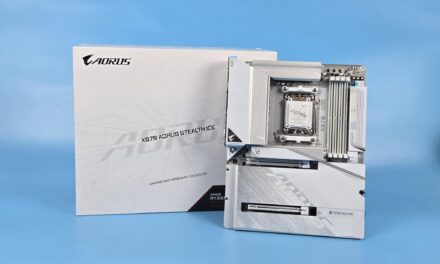
The motherboard comes in a very attractively designed packing box. Packing box itself has the dimensions of 362mm x 302mm x 110mm (L x H x W). Box colors are Black and blood Red which really adds to the looks of the packing. On the front side, we’ve motherboard’s name written on the right side with ROG logo and brand name printed on the top right side. A circuit layout diagram is on the left side. On the bottom we’ve salient features of the motherboard printed like chipset, Intel Optane ready, Nvidia SLI ready, AMD Crossfire ready and Aura Sync.

On the backside, there is a motherboard picture in the center. Specifications are printed on the left side of this picture. On the right side, there are highlights of the board’s features like USB 3.1 Front Panel header, AURA, 2×2 MU-MIMO Wi-Fi and SupremeFX Codec. To the buyer’s interest, a 20% off coupon from CableMod cables info is printed on the bottom side. Asus and CableMod have partnered and are offering buyers of certain Asus motherboards 20% off from the user’s selected cables from the CableMod. 20% off of CableMod cables is a lucrative offer and as such should not be missed if you are an Asus lover and are in the market for a new motherboard.

Once placed horizontally, the front side of the box has a stylishly printed name of the motherboard, the ROG logo, and brand name. Asus is printed in white color on the bottom right side.

The left side of the box while placed horizontally has the Serial No, Part No etc label. Main features of the motherboard are printed in 13 different languages.

Once the box is opened, we can see that the motherboard is placed inside a cardboard box with transparent cover. Removing this box would reveal the accessories box.

Accessories included with the motherboard are:-
- User’s manual
- I/O Shield
- 4 x SATA 6Gb/s cable(s)
- 1 x M.2 Screw Package
- 1 x CPU installation tool
- 1 x Supporting DVD
- 1 x ASUS 2T2R dual-band Wi-Fi moving antennas (Wi-Fi 802.11a/b/g/n/ac compliant)
- 1 x SLI HB BRIDGE(2-WAY-M)
- 1 x ROG big sticker
- 1 x Q-Connector
- 1 x 10-in-1 ROG cable label
- 1 x M.2 bracket
- 1 x Extension Cable for RGB strips (80 cm)
- 1 x ROG coasters
There are tons of the accessories included in the box. Literally, everything that a builder could need is provided by the Asus. Even an HB Bridge for two slot design is included.


Key Features
Before digging into a design and layout of the motherboard, let’s have a look at salient features of the motherboard which should be highlighted.
USB 3.1 Header
With kabylake, there is a phenomenal change in the way how front panel USB ports of the chassis are provided support on the motherboards. Manufacturers have now implemented USB 3.1 header for front panel USB 3.1 on the chassis. Though we’ve yet to see a chassis with USB 3.1 on the front panel, this is definitely a good move coming from the times of the USB 2.0 followed by USB 3.0, all with backward compatibility. Asus has implemented USB 3.1 header using 3 PCIe Gen 3 lanes. Maximum bandwidth that can be having through this connector would be 2GB/s.
AURA
With the release of Skylake architecture, Asus took a different approach and implemented a new technology which they have referred to as AURA. As the name indicates, this technology has everything to do with the lighting on the board; not just lighting but RGB goodness. Main sections of the motherboard like heatsink cover on the back I/O ports, heatsink cover on the chipset have LEDs beneath them. Many of their boards have PCIe lanes’ locking notch done with LED as well like Maximus IX Formula, Rampage V Edition 10 to name a few. Asus has provided software to control all the lighting effects. Next, Asus has implemented Aura headers. Users now can connect their LED strips specially designed for these headers with the motherboard and can have all the lighting of the chassis coordinated with the motherboard’s lighting effect. CableMod has designed many such strips for the AURA headers. Anyone can do that by fulfilling the requirement which is 5050 RGB Multicolor LED Strips (12V/R/G/B) with the maximum power rating of 2A and no longer than 2m. I’ve one such designed LED strip with me as well for the testing purpose.
This does not end here. Next up is AURA Sync. Asus has introduced the AURA Sync in which all components like the motherboard, the graphics cards, the peripherals and the LED strips can be synced with same color effect. This is a great feature to have for sure.
SupremeFX
SupremeFX is the name of the on-board Audio solution from the Asus on their ROG line up motherboards. Asus has added a low-dropout regulator for cleaner power delivery to the SupremeFX S1220 codec, an ESS® Sabre Hi-Fi ES9023P digital-to-analog converter for superior front-panel output, and a Texas Instruments® RC4580 op-amp for high gain with low distortion — which all adds up to audio that envelops you as never before. Using SupremeFX S1220, we’ve 10 DAC Channels, simultaneous 7.1 channel playback, independent 2.0 channel, multiple-stream stereo to front-panel outputs. Delivering all this power are Nichicon capacitors with high precision clock source and switching MOSFETs. We’ve RC 4580 buffer which provides excellent voltage and current for perfect true-to-life tonality and sound imaging. Hardware is backed up by the comprehensive software suite in the form of Sonic Suite III and Sonic Radar III. These software allows the user to custom tailor the sound according to their needs with later software helps the users in identifying the position of the enemy while gaming.
Gaming Network
Asus ROG Maximus IX Code features the very latest Intel® Ethernet (I219-V) for faster, smoother gaming. Intel’s LAN has the serious double advantage of reducing CPU overhead and offering exceptionally high TCP and UDP throughput. Asus has implemented LANGaurd. This helps to ensure the safer, more reliable connections for your gaming sessions. Advanced signal-coupling technology and premium surface-mounting processes join forces to protect Maximus IX Code motherboard’s connection, plus electrostatically guarded and surge-protected components (ESD Guards) for 1.9x greater tolerance to static electricity and 2.5x greater protection (up to 15kV) against surges.
In addition to the Intel Ethernet, Asus has implemented next-level 802.11ac Wi-Fi with 2×2 dual-band 2.4/5GHz antennas for up to 867 Mbps* transfer speeds — and the very latest Multi-User Multiple In Multiple Out (MU-MIMO) technology to ensure that every connected user experiences the best wireless and online speeds.
Backing all this up is GameFirst IV application which optimizes network traffic for faster, lag-free online gaming — and now it supports Multi-Gate Teaming to team up to 4 networks for maximum bandwidth and smooth gameplay. Intelligent mode automatically compiles a database by parsing new app data to ensure that every game is optimized for the best performance. In addition to that, Asus has provided Bluetooth v 4.1.
3D Printing Friendly
Asus with the release of the Kabylake series motherboards has introduced a new feature knows as 3D Printable Accessories. Now, users can customize the appearance of their builds using these 3D printable accessories. At the moment, 3d designs of these categories can be downloaded from the Asus website:
- 2-Way HB Bridge Cover
- Fan Grills
- Cable Combs
- ROG Fonts (Would come handy for Apex users)
- ROG Keychain
Users can download the 3d files from their website, customize it as per the requirements and can take the 3D Prints from their local vendors or printing shops.
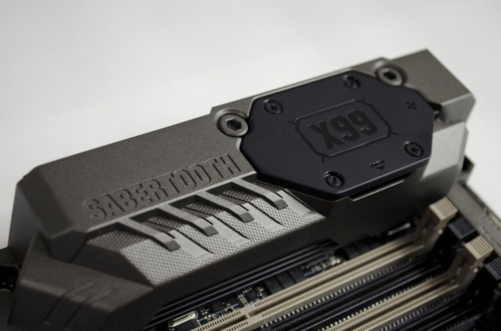
ROG Armor
ROG Armor has been the pinnacle of the ROG Formula series motherboards. This is among their selling features. With Skylake, Asus took a different design and color scheme on their ROG series motherboards. Traditionally, we all expect the ROG in typical Red and Black colors scheme but with Sklylake, were gone those days of the Black and the red. ROG has always been a trend-setter in color scheme. Their new colors are Black and Gray to the extent of the neutral color scheme. And they did it with the success. This neutral color scheme was simply pointing to the industry’s trend of putting RGB LED lighting solution on the boards and let users customize the color scheme themselves. For that scenario, having a neutral color scheme on the motherboard is a must and Asus was ahead of this thinking. Asus has provided a stylish thermal protection that blocks heat from graphics cards and ensures lower system temperatures for better performance and pleasant looks.
Unlike the Formula series motherboards, Maximus IX Code does not have a backplate, plus it does not have EKWB VRM water block. Maximus IX Formula has RGB LED on the PCIe slots as well which are not found on this motherboard. Besides these differences, there is no difference between two boards.
I appreciate this approach from the Asus. Back in Skylake days, when I had my hands on the Maximus VIII Formula, there was a thought in my mind that what if users don’t want to water cool their VRM/MOSFETs yet need the same looks as on the Formula series motherboards. Asus came up with the answer in the form of the Maximus IX Code. Don’t pay for what you are not going to need or use.
OC Design
A dedicated base-clock generator designed for 7th Generation Intel® processors allows overclocked base clock frequencies up to or beyond 425MHz. This custom solution works in tandem with the ASUS TurboV Processing Unit (TPU) to enhance voltage and base clock overclocking control.
With support for DDR4 memory, users are able to drive memory frequencies to 4133MHz (and beyond when overclocked)! ASUS-exclusive T-Topology circuit design plus OC Socket provides a superb memory overclocking capability to unleash the full power of DDR4 by minimizing coupling noise and signal reflection. With innovative equidistant memory channels, it delivers the most balanced control and powerful overclocking compatibility.
WaterCooling Zone
Asus has provided a plethora of water cooling monitoring features on this board. We’ve Water Pump header designated as W_PUMP+. Same can be used for an AIO pump in which case it can be referred to as AIO_PUMP. We’ve two water temp sensors right next to the SATA connectors. Next up is the water flow sensor. To add more functionality to these headers, Asus has broadly implemented them in DC/PWM modes and the user can change the settings in the BIOS.
Asus has provided 5 control sources to base the monitoring of the fan and pump headers on. These are: –
- CPU
- Motherboard
- PCH
- T-Sensor1
- Ext-Sensor (1 to 3)
- Multiple Sources
Please note that in order to set the control source based on Ext sensors, you would need to setup T-Probe sensors on the areas of interest without which these settings would not work.
Asus has provided 8 PWM based fan headers. In addition to that, should there be a requirement of connecting more fans, one can buy Fan Extension accessory from the Asus and it can be connected to the Extension header. Up to three fans can be connected to the fan extension module. 3 probes can also be connected with it. The user will have the control of individual fan in the BIOS. This is simply an amazing detail to the attention that Asus design team has done.
Safety Features and ‘Q’ terminology
Asus has been using the terminology across the board each starting with the Q. All these features pertain to the safety and the handling of the components on the board. Let’s have a look at these. We’ve Q_Slot. This refers to the latches on the PCIe slots. 1-Clip makes it easy to secure or release the graphics card. PCIe slots PCIEX16/x8_1 and PCIEx8_2 have been implemented as SAFESLOT. Manufactured in a single step, a new insert-molding process integrates the slot with fortifying metal for an inherently stronger slot, which is then firmly anchored to the PCB through additional solder points. This provides strength and resistant to the shearing.
Q_LED refers to the on-board LEDs installed on critical areas to show the status of the corresponding component. We’ve CPU, DRAM, VGA, and BOOT LEDs on the board. If any of these components has some issue, the corresponding LED would continuously light up without blinking. This helps in the troubleshooting and diagnosis.
Q_CONNECTOR refers to the supplied accessory which makes the front panel cables handling easy. The user would simply connect the cables on the labelled connector and this whole connector would be installed on the system panel connector on the motherboard.
Q_CODE refers to the two digit display system provided on the top right side of the board. This can be used to help identify the problematic areas in case of any trouble. Q_Code table is provided in the manual for reference.
Q_DIMM refers to the 1-slided clips for ease of installation and removing the RAM modules.
Q_SHIELD refers to the black, nickel coated I/O Shield that would prevent any physical injury to the user while installing the motherboard in the chassis.
Asus has also provided CPU Installation tool which is 1-layer protection from damaging the pins on the CPU socket. This comes handy for less experienced users.
ESD GUARDS refers to the 2 times greater electrostatic protection than standard. ESD Guards cover the USB, audio and LAN ports.
TRUEVOLT USB refers to the two dedicated USB power supplies that provide rock-steady 5V to all USB ports, minimizing power fluctuations for minimal data loss.
Closer Look
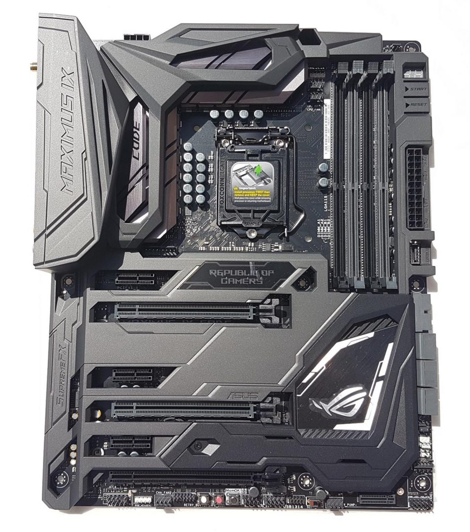
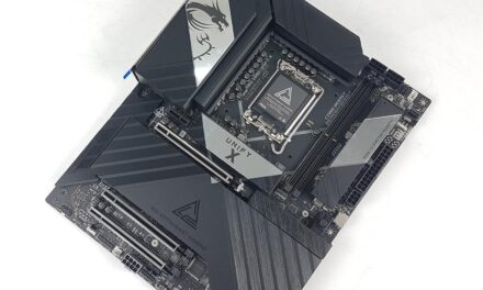
This board is one heck of a design innovation from the Asus design team. I myself am passionate about Asus Formula series motherboards and design of this motherboard is identical to the Maximus IX Formula with few differences which have been highlighted in the Key Features section. We have a regular ATX size PCB in grayish black tone with a beautiful ROG Armor plate or cover on top of it. This cover adds more the overall aesthetics of the motherboard look and feel. CODE is printed on the heat sink cover of the VRM. There is a Republic of Gamer writing right below the CPU Socket which is lit up once it is powered on.

ROG Cover is two toned. Main is light gray while the bottom right side sub-part of it is in a darker tone. This is the removable cover of the M.2 SSD and the chipset itself. Note that ROG eye on the Chipset cover does not light as it does not have LED underneath it. RGB LEDs are implemented on the ROG Armor itself. To remove the ROG Armor, the user would have to unscrew the large size black screws on the backside of the motherboard.

The backside of the ROG Armor shows the RGB LED controllers. One is on the back I/O ports side and the other one is on the backside of the Republic of the Gamers text. Both controllers are connected to the RGB Headers on the PCB of the motherboard.

Text for Power, Reset buttons and LEDs for CPU, DRAM, VGA, BOOT and USB 3.1 are also labelled on the ROG Armor.
Below pics show the M.2 SSD cover removed from the front and the back side. Note the metallic ROG Eye logo implemented on the upper side of the chipset cover. Unfortunately, this part of the cover does not light. To remove this section of the cover, the user would need to remove the only screw right next to the 5th PCIe slot.

Asus has provided two M.2 slots on this motherboard. One is M.2 Socket 3, with M Key, type 2242/2260/2280/22110 storage devices support (both SATA & PCIE mode). This is the socket with the ROG Cover on it.The second one is M.2 Socket 3, with M Key, type 2242/2260/2280 storage devices support (PCIE mode only). This port is implanted vertically on the bottom of the board. It gives enough clearance for up to two cards setup. If you are up to running a 3 way CF of AMD cards then this slot would be rendered useless.

One immediate Con that comes to mind is the implementation of the horizontal M.2 Socket with ROG Armor cover on top of it. One would need to remove the cover to access the socket. If the user intends to remove the SSD or change it after completion of the build, the cover needs to be taken off. But for that, graphics card(s) would need to be removed as well. This can be quite a hassle.
Asus has provided supporting bracket for the second M.2 socket in a vertical orientation. SSD can be mounted on the bracket and bracket can be installed on the board. This would give safety and protection to the SSD.
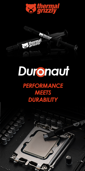
Below pic shows the backside of the PCB.

Back side I/O ports include: –

- 1 x DisplayPort
- 1 x HDMI
- 1 x LAN (RJ45) port(s)
- 1 x USB 3.1 (black)Type-A
- 1 x USB 3.1 (red)Type-C
- 4 x USB 3.0 (blue)
- 4 x USB 2.0
- 1 x Optical S/PDIF out
- 5 x Audio jack(s)
- 1 x Clear CMOS button(s)
- 2 x Wi-Fi antenna port(s)
- 1 x USB BIOS Flashback Button(s)
Note that Audio jacks are gold plated.
Top left and the top sides of the motherboard have beautiful VRM heatsinks under the ROG Armor. Maximus IX is labelled on the ROG Armor on the back I/O Port. Text “Code” is labelled on the left side heat sink which kinda looks good in totality.

8-Pin power connector (EPS) is located on the top of the PCB behind the heatsink cover.

On the top left the most side, we have a Hi-Amp fan connector. It has a power rating of 3A or 12 x 3 = 36W. It can support multiple fans with more power requirement. It is a PWM fan header which can be setup in the BIOS.
Right next to these is the CPU Socket. It is well designed with clearance in mind for large CPU coolers. Foxconn LGA115X is printed on the CPU socket cover. Important instructions are printed on the top of socket cover. This cover needs to be placed somewhere safe after installing the CPU. I prefer to keep such items in the motherboard’s box for ease of access later on. As a general rule of thumb, always keep CPU socket covered. 21 capacitors are visible around the CPU Socket. Power phases will be discussed later in the review.

DIMMs are implemented on the right side of the CPU socket. Clearance is good enough between the CPU socket and the DIMM slots. Asus uses a notion of Q when it comes to implementing various features on the board. DIMM slots are also known as Q-DIMMs. The one end towards the PCIe slots on these slots is fixed while the other end is a tip/latch which gets locked once RAM is installed. To remove the RAM, simply push that latch away from the RAM and pull out the RAM.
Maximum of 4 DIMMs can be installed at a time with the maximum capacity of 64 GB. These are the DDR4 type with 288 pins. DDR4 speed is 2133MHz as per JEDEC specification. This is the confirmed supported speed by the Intel on Broadwell-E, Skylake and Kabylake architectures. Anything above is not guaranteed as it is not JEDEC standard. Hence, manufacturers tend to mention the supported speeds with OC nomenclature. Maximum supported speed on this motherboard is 4133 (OC). Other supported speeds are already mentioned in the specification section of the review. Memory type is DDR4, Non-ECC, un-buffered with Dual Channel architecture. It supports Intel® Extreme Memory Profile (XMP).

Please note that XMP is not loaded automatically but has to be loaded from the BIOS. Also, reported frequency outside of the BIOS would be like 1066MHz. Don’t panic as one would need to multiply the reported frequency with 2 to get effective speed. This example pertains to 2133MHz speed. Rest follows the same convention. This is simply due to the fact that frequency being reported is single data rate whereas we’ve DDR4 where DDR stands for double data rate. Hence the notion of multiplying with 2.
Asus has provided further protection for the DIMM slots by implementing resettable fuse that protects connection ports and DRAM against overcurrent and short-circuits damage.
Right next to DIMM slots we’ve USB 3.0 connector which is implemented in angled direction which comes handy for cable management. Next to it is USB 3.1 connector. Details of the USB 3.1 connector have already been discussed in the Key Features section. Next to the USB 3.1 connector is the 24-Pin EATX power connector which is typical vertical implementation.
Note the CPU, DRAM, VGA and BOOT text printed in front of the 24-pin EATX power connector. These are actually printed on the ROG Armor but they give the look of totality as can be seen from the pic. Very good thinking indeed by the design team. They are printed on the areas with corresponding LED beneath the ROG Armor. Moving further ahead, we have the Reset and Power buttons with black arrow indicators. They are also printed on the ROG Armor. In fact, the buttons have been implemented on the ROG Armor. These also have LEDs underneath to give a glow effect on these buttons which is very eye catching.

Above picture shows the same area with ROG Armor removed. Notice the LEDs right in front of CPU, DRAM, VGA and BOOT texts. Even these texts are printed on the PCB as well so that user may not get confused. Asus seems to be turning no stone unturned.
Two buttons are marked with BTN_LED1 and BTN_LED2. BTN_LED1 is the Power button and its corresponding LED whereas the BTN_LED2 is the Reset button with its LED. Right next to them is the Debug LED which Asus refers to as Q_Code LED. It shows two-digit codes and is very helpful in troubleshooting and identifying the problematic area. This also helps in reducing the time, effort and hassle when troubleshooting. Instead of going through all areas, the user would look up the code in the manual start troubleshooting accordingly.
Also, note that LEDs of the CPU, DRAM, VGA and BOOT are not only status indicators but they also report the problem if any. This in conjunction with Q_Code LED is very effective implementation. Let’s say if there is any error with say RAM then DRAM light will continue to light without a blink unless the problem is resolved. All four LEDs have a different color on them. These are: –
- RED color for CPU LED
- Yellow color for DRAM LED
- White color for VGA LED
- Yellow Green for BOOT LED
Here BOOT refers to booting devices.
We’ve already discussed M.2 sockets, let’s have a look at other storage connectors. We’ve 6 SATA connectors to the right side of the USB 3.0 header. These are labelled as SATA6G_1 to SATA6G_6 where 6G signifies the SATA 6 Gb/s interface. The user can create a RAID 0, 1, 5 and 10 configurations with the Intel Rapid Storage Technology. These connectors are set to AHCI mode by default. Settings can be changed from the BIOS.

Please note that when M.2 socket under the ROG Armor operates in SATA mode, SATA port 1 i.e SATA6G_1 will be disabled. Such limitations are mentioned in the manual. Make sure to read the manual before setting up the system.
We’ve Channel fan header next to the SATA connectors. This is a PWM fan header with the 1A power rating. We’ve LN2 jumper next to this header which is disabled by default. Asus has provided the built-in provision to combat the cold boot during LN2 overclocking for which this jumper needs to be set to active the LN2 mode. Next, we have a two pin T-Sensor. One can connect thermistor cable on this connector and starts monitoring the temperature of the critical areas of the motherboard.
Next, we’ve series of white color connectors which are for water cooling enthusiasts. We have a 3-pin Water Flow connector designated as W_Flow. Next, we’ve 2-pin Water In connector designated as W_IN followed by 2-pin Water Out connector designated as W_OUT. These connectors allow the user to monitor the temperature and flow rate of liquid cooling setup. Next, we’ve 5-pin Fan Extension connector. Fan Extension module can be bought separately from the Asus and up to 3 fans can be connected using this connector. As described earlier, the user would get individual control of all those 3 fans. Again, Asus design engineers have delivered.
Last, we’ve system panel connectors. We’ve 4-pin speaker connector. Speakers are no longer in use but they can still be hooked up nevertheless. Visual error reporting has superseded the audio based error beeps. That was quite a hassle in remembering the number of beeps and accordingly an error area.
Right next to it is the front panel connector. Power LED +/- and Power button cables have to be installed on the top four right most pins. HDD +/- and Reset cables have to be connected on the bottom 4 right most pins.
Let’s have a look at the I/O connectors on the bottom side of the motherboard. Starting from the right side, we’ve system panel connector followed by M.2 Socket. These two have already been discussed. Next up is a Water Pump header designated as W_PUMP+. It is a PWM header which can be setup in the BIOS as per the requirement.
Next up is an SLOW_MODE switch. It is disabled by default. It is used when the LN2 mode is on and LN2 based cooling is being employed. The system may crash due to CPU being unstable when using extreme overclocking. Enabling this button will lower the CPU frequency and helps to improve the system stability. Next up is a USB 2.0 connector followed by the ROG_EXT connector. This connector is used to connect ROG OC Panel and other devices. USB 2.0 1314 on the mid board shares pins with ROG Extension port.
Next up is the Mem OK button. This button comes handy when there is an incompatibility between the DRAM and the motherboard. If the DRAM_LED lights continuously then press and hold this button until DRAM_LED starts blinking. This will attempt to put the system in the compatible mode with the DRAM where possible and to give the user a successful boot. Please note that this is a tuning process and system will try with different failsafe settings of the DRAM which can take some time and during this process, blink speed of the DRAM_LED increases. Give the system time to fine tune itself. This button does not work under Windows.
Next up is SAFE_BOOT button. It can be pressed any time to force the system boot into the BIOS safe mode. This would help retain the previous BIOS settings and comes handy during overclocking. Next up is the ReTry button. It is also beneficial to the overclockers. If during extreme tuning, Reset button becomes useless, RETRY_BUTTON would force the system to reboot itself while retaining the settings.
Next up is a TPM connector. This connector supports Trusted Platform Module system. This system stores keys, digital certificates, passwords and data. TPM module can be bought separately.
Next up is a 4-pin PWM Channel Fan header. Next up is the AURA RGB Header. There are total two connectors on this board. Another one is located on the CPU Socket area above the CPU_OPT_FAN header. These are 4-pin headers. It is used to connect RGB LED Strip with the motherboard. I’ve already discussed these earlier in Key Features section. Next up is the Front Panel HD Audio connector.
Let’s have a look at PCIe slots. This board has total 6 PCIe slots. Slots no 1, 3 and 5 from the top are PCIe Gen 3.0/2.0 x1. The second slot is PCIe Gen 3.0/2.0 x16. This slot is electrically x16 implemented and connected with the CPU. This is an only slot with x16 speed on the board. The fourth slot is PCIe Gen 3.0/2.0 x8. The sixth slot is PCIe Gen 3.0/2.0 x4 and is taking PCIe lanes from the chipset. This slot is taking PCIe lanes from the CPU.

Please note that in the case of two SLI or CF, slot no 2 and 4 will operate at x8/x8 speeds. In case, a graphics card is installed in the 4th slot, slot no 2 will automatically operate at x8. This is because CPUs under LGA-1151 have 16 PCIe lanes on them which have to be shared between 2nd and 4th slots. In case a graphics card is installed on 2nd slot, that slot will operate at full x16 speed. As PCIe Gen 3.0/2.0 x16 is implemented one slot down from the CPU socket, this would give more clearance to the large size CPU coolers.
These slots have been designated as: –
| Slot No | Description |
| 1 | PCIEX1_1 |
| 2 | PCIEX16/x8_1 |
| 3 | PCIEX1_2 |
| 4 | PCIEX8_2 |
| 5 | PCIEX1_3 |
| 6 | PCIEX4_3 |
Digi+
Asus has been using Digi+ technology for quite some time. I did not include this feature in Key Features section deliberately as I intended to cover this feature along with VRM/MOSFET for the power delivery system of the board in the Design section. ROG Maximus IX Code is equipped with ASUS Digi+ Power Control for maxed-out overclocking potential, enhanced system stability and superb power efficiency. Digi+ Power Control is the industry’s leading digital power controller (ASP1257 NSG7 N410P) and it’s fully compliant with Intel’s IMVP8 specifications, for smoother, safer power. We have a PWM controller (ASP1400BT), handling 10 power phases. These phases are implemented using 87350D NexFETs from Texas Instruments, micro fine alloy inductors and 10K capacitors. There are 8+2 Power phases on the Asus Maximus IX Code. 8 phases are dedicated for the CPU. 2 phases are for the iGPU. 2 phases are dedicated to the Memory. We’ve more than adequate phases for stable power delivery to the motherboard and various components. This also helps in stable overclocking.
For our readers who may not know the power phases, here is the brief on that. Power Supply Unit of the PC provides 12V power to the motherboard. This power needs to be converted into the Voltage required by the CPU ranging from 0.5 to 1.5 or so depending upon the architecture and the platform. This stepping is done using the VRMs (Voltage Regulatory Module) on the motherboard. These VRMs are responsible for converting 12V into the Voltages required by the CPU. This conversion results in excessive heat. Hence, the requirement for effective cooling makes sense. Heat sinks on the VRM provide passive cooling. More power phases are a good thing to have. For example, if there are two power phases then each of the power phases would be converting 50% of the voltage. Add two more power phases and each phase would be doing 25% of the load. This not only ensures the fewer loads on each phase but also, less heat generation across phases and consistent power supply to the components. For more details, there are many guides available on the Internet which can be used to understand the concept.
A dedicated base clock generator designed for 7th Generation Intel® processors allows overclocked base clock frequencies up to or beyond 425MHz. This custom solution works in tandem with the ASUS TurboV Processing Unit (TPU) to enhance voltage and base clock overclocking control.
ASUS-exclusive T-Topology circuit design plus OC Socket provides the superb memory overclocking capability to unleash the full power of DDR4 by minimizing coupling noise and signal reflection.
The Energy Processing Unit (EPU) automatically detects and adjusts power consumption according to the rig’s needs. EPU will also reduce CPU wattage to a set level and deliver more savings with the Away mode, creating an extreme energy-saving scenario that shuts down unused I/O controllers and reduces the power consumption of the graphics card.
BIOS
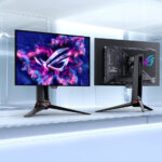
Before discussing the performance of the test build, let’s have a look at the BIOS of the Maximus IX Code. Asus has provided a ton of options in their media acclaimed UEFI BIOS. The graphical interface is easy to navigate through using the mouse and the keyboard. When loaded, Advanced Mode will be enabled. This mode is for the experienced users. For novice users, pressing F7 would load EZ Mode. Extreme Tweaker Menu is loaded on the BIOS startup. It shows the CPU and Memory related critical info like Temps, Clocks, Ratio etc on the right side. On the left side, we’ve to overclock related options. XMP can be loaded from the Ai Overclocker Tuner option.

Main Page shows the BIOS and the CPU information.

The advanced menu has CPU, PCIe, USB, Storage, Power related settings.

Monitor menu has the temperature monitoring of CPU and other areas of the motherboard. Fan speeds are also reported here. In addition, we’ve settings to control individual fans.


Boot Menu contains settings for Fast Boot, Storage drives priority, Boot media etc.


Tool menu has BIOS EZ Flash Utility 3, Secure Erase, Overclocking profile, SPD Info, Graphics Card info.

There are multiple ways to update the BIOS on this board. On the back I/O port we’ve USB BIOS Flashback port. Bottom USB 3.0 port is designated for this purpose. Download the BIOS file from the Asus website. Rename it M9F.CAP Does ‘F’ ring any bell? Yes, same BIOS file for Formula and Code as PCB of the both the boards is the same. Copy that M9F.CAP file to the root directory of the FAT32 formatted flash drive. Connect the flash drive to the designated port and press and hold the BIOS flashback button (Button with BIOS text on I/O Port) until flashing light appears. The light will continue to flash until the process is done successfully. Do this process with the system powered off. Once the light goes out, press the BIOS Reset button and power on the system.

Another way around is to use the AZ Flash utility in the BIOS. It can even download the BIOS file from the internet and update the BIOS. Updating the BIOS is a risky process and as such should only be done when encountered any issue whose resolution is in updated BIOS.
A third way of updating the BIOS is through EZ Update software when in Windows environment.
Secure Erase is used to erase the SSD contents and to restore the SSD to factory default.

Overclocking Profile helps the user to save several profiles with different settings and to load the saved profile when needed. Up to 8 profiles can be saved.

ROG OC Panel H-Key Configure contains settings to be used in tandem with ROG OC Panel.

Asus SPD Information shows the DRAM info.

Graphics Card Information shows the info of the installed graphics card. GPU Post will show the graphical interface of the PCIe slots with info on the installed graphics card(s).


Exit Menu has related options like Exit without saving, Exit with saving, Load optimized Defaults etc.

Pressing F3 will load the Favorites menu where the user can save the most frequently used settings for ease of accessing.

Pressing F6 will load Q-Fan Control. The user can create custom fan curve on each fan or group of fans depending upon the implementation of fan headers on the motherboard.

Pressing F7 would load the EZ Mode. EX Tuning wizard can be used to maximize the performance of the PC depending on the cooling solution being used.


Software
AiSuite III
Asus has bundled much software in the provided CD disk. I’ll discuss AiSuite III here as it is the main software when it comes to getting best of the best performance and fine tuning. The user can use this software to do literally anything ranging from overclocking to controlling fans to updating software and BIOS etc.

The main interface has One Click Overclocking option on the top left side. Click it and 5-way digital optimization will start. There are three modes on its right side, namely: Performance, Power Saving and Away Mode. Away Mode is a more tightened version of the Power Saving mode.
We’ve TPU, Fan Xpert and Digi VRM summaries on the main section. Turbo App status and EPU settings are on the right side of the main section. CPU Frequency, Voltages, Temperatures and Fan speeds are mentioned on the status bar located at the bottom of the interface.
Clicking on the three bars and an arrow indicator on the left most side will open the menu list of the software.

It can be seen that there are a ton of settings that this application provides. We’ve TPU, EPU, Digi+ VRM, Fan Xpert, PC Cleaner, EZ Update etc on the listing.
Fan Xpert is a very handy tool and it can be used to configure each and every fan in the Chassis as per the user requirement. If you are not sure about the settings to be used then simply run the Fan Xpert Fan tuning wizard. The wizard will check the characteristics of each fan and set the profile accordingly. There are 4 pre-built profiles for the fans which are Silent, Standard, Turbo and Full speed.

The graphical interface is available as well to set the fan curve. There are two modes, smart Mode with custom fan curve and RPM Fixed Mode which will set the one constant speed for the selected fan.
TPU section provides comprehensive settings to overclock the CPU. We have the option of fine tuning single core or group of cores. Voltage can be set as Adaptive, offset or User where User means the manual Vcore.


Digi+ VRM section contains settings like CPU Load Line Calibration, VRM Switching Frequency, CPU Power Phase control etc.

Clicking on 5-Way Digital Optimization will start a tuning wizard that would overclock the CPU frequency with 100MHz at a time with stress test of 15 Seconds or user provided value on each iteration to determine the thermal characteristics and stability. The system will restart several times during the process. The process is fully automatic and user intervention is not needed.

Each iteration shows the summary of the process in terms of Current-Voltage, Temperature and Power in addition to the Maximum values of each variable. Once the complete process is done, Summary will be produced.

System Information shows the Motherboard, CPU and DRAM information.

Turbo App boosts the performance of selected applications.

PC Cleaner lets the user to get rid of junk files and to free the space taken by these files.

EZ Update lets the user update the BIOS of the motherboard and other apps.

USB BIOS Flashback lets the user to check and download the latest BIOS and copy it to the supported USB Flash drive which then can be used to update the BIOS by using the methods already described under BIOS section.

File Transfer is another feature which is based on cloud computing. It lets the user transfer the files between supported mobile devices and the PC. I’ve used this utility to transfer files from and to my Android device to the PC. It needs an active WiFi connection to do that. Files can be shared using Could Go as well so as to make your files accessible from the cloud server.

Test System and Methodology
Testing System
Following system was used to test the functionality and the performance of the Motherboard:
- Intel i7 7700k
- Asus Maximus IX Code
- Asus Strix Rx 480 O8G
- Corsair Vengeance 4x8GB @ 2666MHz RED LED
- Corsair H100i V2
- Corsair ML Pro 120 RED LED
- Zotac T400 120GB SSD
- Western Digital 6TB Black HDD
- ThermalTake Tough Power DPS-G RGB 750W PSU
Microsoft Windows 10 x64 Pro was used for all the testing. The system takes approx 8 minutes with Windows installation. This does not include the drivers/software installation time.
Crimson 17.4.1 drivers were used for graphics card testing.
Following software were used for performance evaluation: –
Storage Drive Tests:
- AS SSD
- ATTO
- Crystal Disk Mark
CPU Tests:
- Cinebench R15
- GeekBench 4.0.3
- 7-Zip
- Fritz Chess
- Handbrake
- SiSandra CPU
Memory Tests:
- AIDA64 Extreme
- SiSandra Memory
- SuperPi
Overall System Tests:
- PCMark
- Performance Test
For gaming and synthetic bench of the graphics card following software were used:-
- 3dMark
- Rise of the Tomb Raider
- Grand Theft Auto – V
- BattleField 1
- DOOM
BenchmarK Results
PCMark is a comprehensive application suite to measure the overall performance of the system and the storage devices. Our test build performs relatively well.

Performance Test or pTest is another comprehensive suite which measures the overall performance of the PC along with detailed tests for each component. I used it to measure the performance of the CPU and the Memory. Scores fall in 94-99% percentile which is a good indication of the performance.

Cinebench is a real-world cross platform test suite that evaluates your computer’s performance capabilities. CINEBENCH is based on MAXON’s award-winning animation software Cinema 4D, which is used extensively by studios and production houses worldwide for 3D content creation. MAXON software has been used in blockbuster movies such as Iron Man 3, Oblivion, Life of Pi or Prometheus and much more. CINEBENCH is the perfect tool to compare CPU and graphics performance across various systems and platforms (Windows and OS X).

Geekbench 4 measures system’s performance across multiple platforms. Our system performs very well under this test.

Frtiz Chess Benchmark is a CPU Performance test. It puts the CPU at 100% utilization and scales among the cores and the threads. The score is recorded as Kilo Nodes per Second and Relative speed.

7-Zip is a compression benchmark which utilizes the Memory bandwidth and CPU Cores to measure the performance which is relative.

Handbrake is transcoding tool which is quite popular among the content creators and it is also used to test the CPU performance and its overclocking performance as well. I used a 5GB 1080p 27FPS MKV file and converted it into an 869MB MP4 480P 23FPS using H.264. The lesser the time is preferable.

Super PI is a single threaded benchmark ideal for testing pure, single threaded x86 floating point performance and while most of the computing market has shifted towards multithreaded applications and more modern instruction sets, Super PI still remains quite indicative of CPU capability in specific applications such as computer gaming. The lesser the time is preferable.

AIDA64 is another extensive application suite to measure the performance and testing the system’s stability. I used it to measure the Memory bandwidth.

SiSandra is another comprehensive application suite to measure the performance of the various components of the PC and to check for any reported issues with them. It uses a graphical representation as well as the performance measure. I used it for CPU and Memory testing.


CrystalDiskMark is a popular tool to measure the sequential and Random Read and Write speeds of the storage drive(s).

ATTO has created a widely-accepted Disk Benchmark freeware software to help measure storage system performance. As one of the top tools utilized in the industry, Disk Benchmark identifies performance in hard drives, solid state drives, RAID arrays as well as the host connection to attached storage.

AS SSD software tests the sequential or random read/write performance of the storage drive(s) without using the cache. AS SSD Benchmark reads/writes a 1 GByte file as well as randomly chosen 4K blocks. Additionally, it performs the tests using 1 or 64 threads and it determines the SSD’s access time.

3DMark includes everything you need to benchmark your PC and mobile devices in one app. Whether you’re gaming on a smartphone, tablet, notebook, or a desktop gaming PC, 3DMark includes a benchmark designed specifically for your hardware.

I tested 4 games on the test build. All the games were tested with their highest graphics settings except that of MSAA which was 4x where applicable. Resolutions of 1080p and 1440p were used.

Overclocking
With 7700k, Intel has achieved yet another milestone which is to enable the users to achieve 5.0 GHz magical figure out of the box using traditional cooling solution. Bear in mind that thermal characteristic of every chip is different and there is no guarantee that chip would hit or cross 5.0GHz. It is still a silicon lottery at large.
I was able to achieve 5.0GHz at 1.310V. AiSuite III’s 5-Way digital optimization achieved 4.7GHz. I’m a sort of person who always prefers to do overclocking manually. Asus UEFI BIOS has tons of settings for overclockers.
The stability test was conducted using Asus RealBench 2.4 software and RealTemp was used to monitor the temps. Max it hit was 81C under stress test. Room temp was 35C. Keeping in mind the room temp, 81C max was a good achievement. Delidding and the more powerful cooling solution would definitely help to bring these temps down.
Cinebench was run to test the overclocking results.

Final Thoughts
The Asus Republic of Gamers is a famous brand among the overclocking enthusiasts and gamers alike. These boards are feature rich packed and provide ultimate performance levels with intuitive UEFI BIOS with a user-friendly interface. Asus ROG Maximus IX Code is the third from the top in the line of Kabylake series, following Maximus IX Extreme and Maximus IX Formula. There are only a few differences between Maximus IX Code and Maximus IX Formula. If you are torn between these two motherboards and not up to water cooling VRM/MOSFET then Maximus IX Code is the one you should look for. This motherboard is feature rich. With 10+2 power phases, ROG Armor, MU-MIMO WiFi module, two M.2 sockets, 6 SATA ports, maximum of 4133MHz of DDR speed, SupremeFX audio solution, USB 3.1 front panel connector, Q_LEDS, 14 USB ports including mid-board, support for multiple graphics cards, AURA Sync, ROG Exclusive features, this motherboard is one heck of a solution for the enthusiasts. The look and feel of ROG Armor design matching it with Formula line up of the motherboards is a plus.
The implementation of the ROG Armor has two limitations. To replace the CMOS battery, one would need to take the entire ROG Armor off. To install the M.2 SSD on socket 1 which is implemented horizontally on the PCB, one would need to take off the M.2 SSD cover. Make sure to install the SSD first before installing the graphics card, otherwise, you would end up regretting not putting the SSD in the first place. There is no backplate on this motherboard though this is not a complaint but the user should know. There are not RGB LEDs on the PCIe slots.
Value:
Asus Maximus IX Code is listed at $290 / PKR 36,500 at the time of the review. The motherboard is definitely expensive but it is worth it for features it carries and performance it offers.
Performance:
During my testing, I did not encounter any issue. First boot was a success. The BIOS has no glitch. I was able to overclock the chip to 5.0GHz at 1.310V though any further attempts to overclock it were not fruitful as I lack adequate cooling to handle high Vcore and resultantly higher temps. This is a phenomenal design packed with power performance punch that has me saying that it is a must have motherboard if you can afford it.
Asus Maximus IX Code has won our Performance and Must Have awards. Though it is an expensive motherboard but if you could afford it, you would simply love it.


Thanks to the Asus Pakistan for providing their Asus Maximus IX Code for the review purpose.


